Pulse Width Modulation With An LED
This example will guide you through the process of connecting an LED to your imp, and controlling its brightness with Pulse Width Modulation (PWM). PWM just means we’ll be sending a series of pulses to the output pin. By varying the length of the pulses with pin.write() we can affect how much power the LED gets, which will change how bright it is. Take a look at the PWM Wikipedia page to learn more about PWM, and what it can be used for.
This example assumes you have a basic familiarity with Electric Imp’s impCentral™. We suggest working through our Getting Started Guide before trying this example.
What you will need
Note The following instructions were written with the imp001 in mind, but they can be readily adapted to any other imp and breakout board.
For this example you are going to need the following:
- 1 x April board
- 1 x imp001 card
- 1 x breadboard
- 1 x red LED
- 1 x 330Ω resistor
- 1 x jumper wire
Circuit
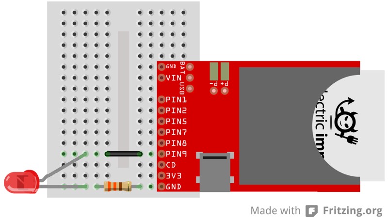
Hook Up Instructions
- Connect the LED’s anode to pin9 through the jumper wire
- Connect the LED’s cathode to GND through the 330Ω resistor
See the Digital Output example for more information about LED polarity and selecting the right resistor.
Code
In impCentral, create a new Product called “Examples” (if you have not tried another of these basic hardware examples) and a new Development Device Group called “led-pwm”. Assign your device to the new Device Group, then copy and paste the following code into the code editor’s ‘Device Code’ pane and hit ‘Build and Force Restart’.
Note This code assumes you’re working with an imp001. For other imps, you will need to modify the name of the pin aliases in line 3. For the imp005, you will also need to modify the PWM parameters in lines 8 and 9 (see pin.configure()).
What’s going on
This example code should pulse your LED on and off every few seconds. Here’s how it works.
The first thing we do is assign hardware.pin9 to a global variable and then configure it to be a PWM_OUT:
led <- hardware.pin9;
led.configure(PWM_OUT, 1.0/400.0, 0.0);
The configure function for a PWM_OUT takes two extra parameters. The first parameter is the period of each pulse — the inverse of the pulse frequency. We want to drive LEDs at around 400Hz, so we divide 1.0 by 400.0 to get the period. Usually, we would add the constant to the code, ie. 0.0025, as this is more efficient, but we’ve retained the calculation here for clarity.
The second parameter is the initial ‘Duty Cycle’, the proportion of the ‘on’ during in the period. We can modify the duty cycle with a pin.write() meaning that this is essentially the initial value we want to write to the pin. Since our example starts with the LED off, we set it to zero.
Once the LED is configured, we can easily control its brightness with a pin.write(). We pass a float (between 0.0 and 1.0) that corresponds to how bright we want the LED to do — ie. if we wanted the drive the LED at 50 per cent brightness, we would use:
led.write(0.5);
Now that we’ve configured the LED and understand how to change the brightness, let’s do something interesting. We’re going to create two global variables that we’ll use to track and modify the brightness:
ledState <- 0.0;
ledChange <- 0.05;
The first variable, ledState, will track the current value of the pin. The second variable, ledChange will control how much we’re changing the pin each pass of our function.
function pulse() {
    led.write(ledState);
    ledState = ledState + ledChange;

    if (ledState >= 1.0 || ledState <= 0.0) ledChange = ledChange * -1.0;

    imp.wakeup(0.05, pulse);
}
This function slowly changes the brightness of the LED by modify the value of ledState each time the function executes. Whenever ledState changes, we make sure it hasn’t gone out of bounds: above 1.0 or below 0.0. If it has, we flip the value of ledChange from 0.1 to -0.1, or -0.1 to 0.1.
Finally, we call pulse() once to get the loop started:
pulse();