dfsdm
Availability
Device
Description
The dfsdm object represents a digital filter for sigma-delta modulators (DFSDM). It is instantiated automatically, but is only available on the imp004m and, from impOS™ 42, the imp006.
impOS provides a single DFSDM input driven by two signal pins:
| Clock Pin (CLK) | Data Pin (DATA) | |
|---|---|---|
| imp004m | S | R |
| imp006 | Q | P |
When using DFSDM, both of these pins are configured as inputs. DATA is fed with the bit stream output by an external sigma-delta modulator at the same frequency as the CLK pin is driven. The external sigma-delta modulator may or may not output this clock signal. If the sigma-delta modulator does not output a clock signal, the host imp can provide one itself by routing a PWM pin to both the sigma-delta modulator and back into CLK. Alternatively, an external clock can be used to drive both the sigma-delta modulator and CLK.
DFSDM Background
Sigma-delta modulators are an alternative to traditional analog to digital converters.
An ADC converts analog signals to digital by sampling the absolute value of the analog signal at a fixed frequency. A multi-level quantizer is used to convert each sample into a digital representation at a preset bit depth. This method suffers from quantization errors in the digital output, experienced as noise. ADC functionality is provided by the imp API’s sampler object.
By contrast, a sigma-delta modulator measures the difference (delta) between two samples of the analog signal over a specified time period and encodes it as a stream of digital pulses (0 representing a negative delta and 1 representing a positive delta). The delta is added back (sigma) to the analog signal through a 1-bit DAC, and the resulting signal issued as a bit stream. This results in much-reduced quantization noise.
The bit stream from a sigma-delta modulator is then passed through a digital filter within the host imp in order to create a digitized sample at the required bit-depth. This approach to analog to digital conversion makes the dfsdm very versatile when compared to a traditional ADC, as varying bit depths and effective sample rates can be achieved simply by adjusting the digital filter parameters.
Another advantage of using dfsdm rather than sampler is that analog components can be removed from the circuit design, thereby reducing the risk of interference from radio transceivers such as WiFi and Bluetooth.
Operation
An imp’s dfsdm behaves very much like the sampler object, both in terms of how it is configured and how it operates. The dfsdm object is set up using the dfsdm.configure() method, which takes as parameters the desired digital filter settings, and an array of blobs as buffers. Each time a buffer is filled with data, a buffer-processing callback function is executed and passed the filled buffer. This callback is registered using dfsdm.configure(). Optionally, the buffers can be pre-processed with a selection of audio processing filters.
While the sampler provides 16-bit samples, dfsdm is capable of producing samples of up to 24 bits in depth. Without any pre-processors specified, dfsdm will provide buffers of 24-bit unsigned samples in the least significant bits of Squirrel 32-bit signed integers. An additional pre-processor is provided to convert these 24-bit samples into 16-bit samples, two of which are packed into each 32-bit word.
The digital filter has three configurable parameters: the filter order, the decimation rate and the integration rate.
The filter order can be interpreted as the number of levels of feedback provided, where a single level of feedback comprises a 1-bit DAC that feeds the sampled delta back to the original analog signal. Different filter orders result in different frequency response characteristics of the resulting output. The quantization noise arising from the conversion is arranged to be present in a different part of the spectrum than the signal of interest. It is through this technique, sometimes known as ‘noise shaping’, that the approach employed by DFSDM can achieve a much better signal to noise ratio than a traditional ADC, especially as bit depth is increased.
The decimation rate is the number of times the signal is oversampled. The higher the decimation rate, the lower the effective sample rate for a given resolution (bit depth).
The integration rate is the number of times the output is oversampled. The effective sample rate and resolution are affected by the integration rate in the same manner as the decimation rate: higher integration rates will decrease the sample rate, but increase the resolution.
To determine the effective output sample rate, the frequency of the clock is divided by the product of the decimation and integration rates:
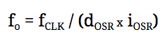
For example, if a 48kHz output sample rate (fo) is required, a clock of 3,072,000Hz could be driven to the CLK input pin (fCLK), and the filter could be configured with a decimation rate (dOSR) of 32 and an integration rate (iOSR) of 2.
Since CLK is not configured by the API, and may be coming from an external source, the sample rate cannot be determined prior to commencing operation. However, once at least one sample has been collected, the effective sample rate can be retrieved via dfsdm.getsampleratehz().
Three additional parameters are provided in the API when configuring dfsdm: the DC offset correction applied to the sample, the clock edge (rising or falling) on which the bit stream is sampled through DATA, and the number of bits by which the resulting sample is shifted right in the output.
Calculating the bit-depth of the output
When using DFSDM without any of the optional audio processing filters, the signed samples are provided in the least significant 24 bits of a 32-bit word. The effective bit-depth of these samples is determined by the filter parameters passed to dfsdm.configure() by the following relationship:
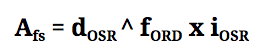
Where Afs denotes the maximum value that can be sampled by DFSDM, dOSR is the decimation rate, fORD is the filter order and iOSR is the integration rate.
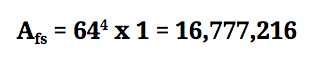
For example, if we choose a fORD = 4, we get a fourth-order filter. The maximum value that can be sampled is calculated by raising the decimation rate dOSR to the power of the filter order, then multiplying by the integration rate iOSR. Let’s say we choose decimation rate 64 and integration rate 1:
The filter parameters should be carefully selected to achieve the desired output bit-depth and sampling frequency.
Audio Applications
When using DFSDM for audio applications, in conjunction with the optional audio processing filters, care should be taken to ensure that samples result in a 24-bit value. The ‘audio packing’ filter DFSDM_PACK_AUDIO assumes a 24-bit signed input, and will produce confusing results if this is not the case.
The following table shows how choice of the filter order and decimation rate affect the maximum value that can be sampled:
| dOSR | fORD = 0 | fORD = 1 | fORD = 2 | fORD = 3 | fORD = 4 | fORD = 5 |
|---|---|---|---|---|---|---|
| x | 2x2 | x | x2 | x3 | x4 | x5 |
| 4 | 32 | 4 | 16 | 64 | 256 | 1024 |
| 8 | 128 | 8 | 64 | 512 | 4096 | 32768 |
| 32 | 2048 | 32 | 1024 | 32768 | 1048576 | 33554432 |
| 64 | 8192 | 64 | 4096 | 262144 | 16777216 | 1073741824 |
| 128 | 32768 | 128 | 16384 | 2097152 | 268435456 | OVERFLOW |
| 256 | 131072 | 256 | 65536 | 16777216 | OVERFLOW | OVERFLOW |
| 1024 | 2097152 | 1024 | 1048576 | 1073741824 | OVERFLOW | OVERFLOW |
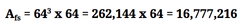
The integration parameter iOSR also has an effect on the maximum sample value, and values from the table should be multiplied by iOSR to determine this value. For example, a third-order filter with a decimation rate of 64 and an integration rate of 64 would achieve the following maximum sample value:
Note that the right-shift parameter can be useful when large maximum values are achieved, in order to bring the result back into the range of a 24-bit value. For example, a fifth-order filter with decimation rate 32 and integration rate 2 will produce a maximum value of 67,108,864. By specifying 2 as the right-shift value, after the integration rate has been applied, samples will be divided by 4, resulting in a maximum sample of 16,777,216.
Using DFSDM and SPI on the imp004m
Please note that if you wish to make use of dfsdm, you will not be able to make simultaneous use of spiAHSR, and vice versa. This is due to the way these objects make use of DMA. The imp004m’s spiGJKL is unaffected by this limitation. It is possible to use the two objects within your application, but your code will need to ensure they are not used at the same time.
You cannot call dfsdm.configure() while spiAHSR is configured and enabled, so if you are making use of this SPI bus, you should call spiAHSR.disable() before calling dfsdm.configure(). Equally, if you are using dfsdm and need to then make use of spiAHSR, you will need to call dfsdm.stop() (to send the current buffer to the buffer-processing callback) and dfsdm.reset() (to disable the dfsdm) before calling spiAHSR.configure().
If you attempt to configure dfsdm while spiAHSR is in use, the following error will be thrown: “cannot configure dfsdm whilst spiAHSR is in use in dfsdm.configure(filterOrder, decimation, integration, offset, rightShift, samplingEdge, buffers, callback[, processors])”. If you attempt to configure spiAHSR while dfsdm is in use, the following error will be thrown: “cannot configure spiAHSR whilst dfsdm is in use in spi.configure(flags, rateKHz)”.
Member Entities
The dfsdm object has the following member methods:
- dfsdm.configure() — Configures the imp for sampling
- dfsdm.getsampleratehz() — Returns the imp’s effective sample rate
- dfsdm.reset() — Resets the imp004m’s DFSDM facility
- dfsdm.start() — Begins sampling
- dfsdm.stop() — Halts sampling