Digital Output
This example will guide you through the process of connecting an LED to your imp, and controlling it as a DIGITAL_OUT.
This example assumes you have a basic familiarity with Electric Imp’s impCentral™. We suggest working through our Getting Started Guide before trying this example.
What You Will Need
Note The following instructions were written with the imp001 in mind, but they can be readily adapted to any other imp and breakout board.
For this example you are going to need the following:
- 1 x April breakout board
- 1 x imp001 card
- 1 x breadboard
- 1 x red LED
- 1 x 330Ω resistor
- 1 x jumper wire
The Circuit
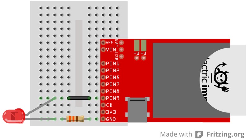
Hook Up Instructions
- Connect the LED’s anode to pin9 through the jumper wire
- Connect the LED’s cathode to GND through the 330Ω resistor
The LED’s anode is the positive side of the LED, while the LED’s cathode is the negative side. The lead (or leg) of the LED’s anode should be slightly longer than the lead of the LED’s cathode.
Selecting the Resistor
We use Ohm’s Law to determine what resistor we should use for the circuit (the values for your LED might be different):
- Supply Voltage 3.3V
- LED forward voltage 2.0V
- LED Current 4mA (the imp’s pins can only source 4mA)
Ohm’s Law
V = I × R
3.3V - 2.0V = 4mA × R
R = 1.3V / 0.004A
R = 325Ω
The closest common resistor value to 325Ω is 330Ω.
Code
In impCentral, create a new Product called “Examples” (if you have not tried another of these basic hardware examples) and a new Development Device Group called “led-blink”. Assign your device to the new Device Group, then copy and paste the following code into the code editor’s ‘Device Code’ pane and hit ‘Build and Force Restart’.
What’s Going On
The first thing we do in code is assign hardware.pin9 to a global variable called led. This will make the pin easier to reference in the rest of the code:
led <- hardware.pin9;
Next, we configure the pin to be a DIGITAL_OUT pin with pin.configure(). From impOS™ release 30, this call takes a second parameter: the start state of the pin:
led.configure(DIGITAL_OUT, 0);
A pin that is configured to be a DIGITAL_OUT pin will have a voltage of 3.3V when we set the pin high with pin.write(1) It will have a voltage of 0V when we set the pin low with pin.write(0).
Once the pin is configured, we create a global variable called state to track whether the LED is on or off. This matches the initial state set in the previous line:
state <- 0;
Finally, we create a function, blink(), that will change the state of the LED pin every half second. The first thing the function does is flip the value of state:
if (state == 0) {
    state = 1;
} else {
    state = 0;
}
Once we’ve flipped the value of state, we write it to our LED pin:
led.write(state);
And finally, we tell the imp to run the blink() function again in 0.5 seconds with imp.wakeup():
imp.wakeup(0.5, blink);
Once we have our function defined, we need to call it once to get the blinking started:
blink();
After that it handles itself, since we schedule blink() to run again at the end of the blink() function.