Working With Audio On The imp004m
How To Record And Play Digital Sound
The imp004m module can work with external hardware to both digitize an audio signal and to convert digital audio data back into an analog signal capable of driving a speaker or earphones: emulation of a fixed-frequency DAC using pulse-width modulation (PWM), and support for filtering the input from a digital microphone which together enable sampler-like functionality. Together, these audio processing capabilities put the low-cost imp004m on a par with other imp modules.
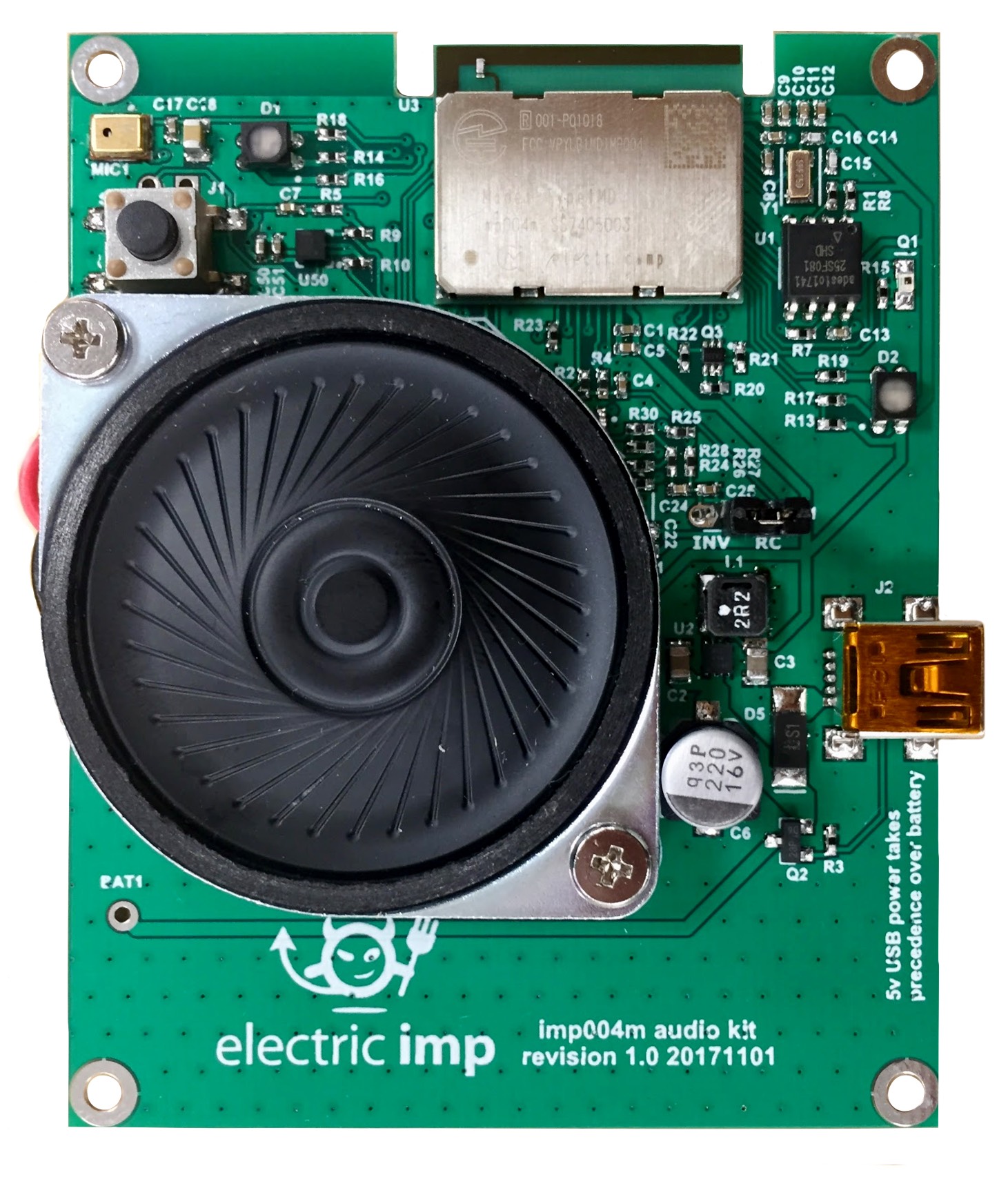
This guide will provide you with an introduction to working with audio during the development of imp004m-based products that require this functionality. Electric Imp has produced the imp004m Audio Kit board (above) to help customers explore the imp004m module’s audio input and output capabilities.
The imp004m Audio Kit
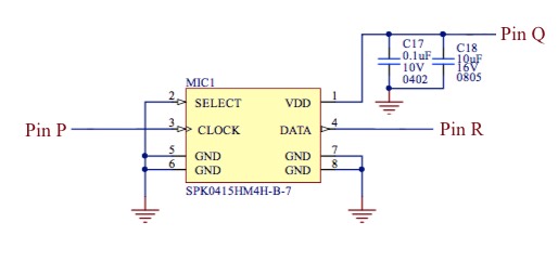
The imp004m Audio Kit includes an on-board Knowles SPK0415HM4H-B-7 MEMS microphone for input. It is powered by the imp004m’s pin Q and receives a clock signal sent from pin P. Pin R takes the signal from the microphone.
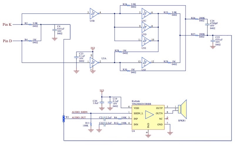
In the opposite direction, audio is output from pins K and D: respectively, the most-significant byte and least-significant byte of the PWM. The output from these two pins passes through a filter circuit and is then fed into a Richtek TPA2006D1DRBR 2.65W Class-D amplifier, which drives the Audio Kit’s speaker terminals:
Digital Filters
The Audio Kit incorporates two digital filter circuits between the PWM output and the Richtek amplifier. The first of these simply comines the two 8-bit PWM signals to gain the full 16-bit resolution. This is done by passing the two signals through resistors R2 and R4, and across a grounded capacitor, C4 (a ‘summing junction’). This yields the signal AUDIO_OUT_RC:

The ratio of the two resistances, R2 : R4, is 2 ^ per PWM output bit depth = 2 ^ 8 = 256. A choice of 1MΩ and 3.9KΩ resistors gives this ratio. Note that the higher the resistance ratio, the higher the resistor accuracy we require, in this case 100 * 1 / 256 = 0.39%.
C4 is a low-pass filter capacitor; its value depends on your application (and the input impedance of whatever you’re driving). The value of capacitor is determined by the formula:
1
-------------
2 π R2 fc
where fc is the low-pass filter’s cut-off frequency.
This is a simple, low-cost approach. The second circuit, which outputs as AUDIO_OUT_BUFF, uses the same principle but adds digital logic to yield a better output:
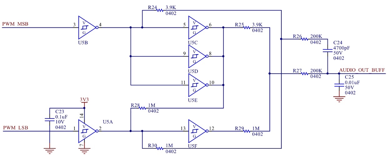
Here six external digital switches are arranged in three groups — U5B and U5A; U5C, U5D and U5E; and U5F — to divide the circuit’s output resistance by three. All digital circuits have a finite output resistance which changes the effective resistance of the filter leading to a loss of resistance accuracy and therefore lower the effective bit depth of the output signal. This circuit significantly minimizes this effect.
Three digital switches (U5C, U5D and U5E) are also used to invert the original signal, run it through a high-pass filter and then combine it back with the non-inverted signal. At high frequencies, the two signals will cancel out, helping to attenuate the PWM frequency.
In addition, the circuit has its own power supply (3V3 into U5A) which can be separate from that used to feed the imp. This means the power line is quieter and thus a lower noise floor.
Though the second, more sophisticated circuit is higher quality output, this sophistication clearly comes at a much greater BoM cost. Your application will determine which of these you will use in your own product, but the Audio Kit provides both — use jumper W1 to select whether AUDIO_OUT_RC or AUDIO_OUT_BUFF is fed into the amplifier — to allow you to assess their pros and cons in the light of your application.
- More detailed information about this filter design can be found at EDN.
Additional Audio Kit Features
In addition to the Audio Kit’s sound processing functionality, the board also includes an RGB LED for application-controlled feedback, and an LIS2DH12TR three-axis accelerometer to assist in the development of applications for which audio might be used to provide notifications to end-users of sensor-driven threshold-crossing events. The Audio Kit is also capable of being driven by battery power.
For more information on these extra features, and for board schematics and other details, please see the imp004m Audio Kit Reference Design page.
The imp004m Audio Architecture
If you have not worked with audio on an imp-enabled device before, please first take a look at the guide ‘How to use Samplers and Fixed-Frequency DACs’, which describes the imp’s audio IO architecture. While reading the guide, it’s important to bear in mind that, unlike other imps, the imp004m does not possess a true fixed-frequency DAC, though it is able to emulate one and thus gain access to the imp API’s fixedfrequencydac object. The imp004m has no sampler, but instead provides a new object, dfsdm, to use in its place.
Whether your application requires audio input or output — or both — the imp004m will also require extra hardware to allow you to feed the dfsdm object with an audio signal to digitize, and the fixedfrequencydac instance with a suitable external filter circuit to remove DC bias. The imp004m Audio Kit provides all of these additions.
Audio Input Using DFSDM
Though the imp004m makes use of the existing impOS fixedfrequencydac instance for audio output (updated for the module’s hardware, of course), for audio input it does not use an updated version of the sampler object provided by other imps. In fact, applications on the imp004m will throw an error if you attempt to make use of sampler. Instead, you should use the imp004m’s dfsdm object. However, if you have used sampler before, dfsdm’s methods will be familiar to you.
The dfsdm object represents a digital filter for sigma-delta modulation (DFSDM), which is an alternative to an analog-to-digital converter (ADC). Instead of sampling the absolute value of an analog signal at fixed intervals, as a traditional ADC does, the sigma-delta modulator measures the difference (delta) between two samples of the analog signal over a specified time period and encodes this difference as a series of digital pulses. This stream is added back (sigma) to the analog signal through a 1-bit digital to analog converter, and the resulting signal issued as a bit stream which is passed through a digital filter within the imp004m to create a digitized sample at the required bit-depth.
This approach to analog to digital conversion makes the DFSDM very versatile when compared to a traditional ADC, as varying bit depths and effective sample rates can be achieved simply by adjusting the digital filter parameters. For imp004m-based products, DFSDM means that analog components aren’t required in the circuit design, thereby reducing cost and minimizing the risk of interference from radio transceivers such as WiFi and Bluetooth.
dfsdm is instantiated automatically as a property of the hardware object to provide a single DFSDM input using two pins: a clock on pin S and audio on pin R.
On the imp004m Audio Kit, these pins are connected to the on-board MEMS microphone, which receives power from the imp004m’s pin Q, which therefore needs to be configured as a digital output initially set high:
hardware.pinQ.configure(DIGITAL_OUT, 1);
In addition, you will need to send a clock signal to the microphone. The microphone’s clock pin is connected to the imp004m’s pin P, through which you should provide a suitable PWM output:
hardware.pinP.configure(PWM_OUT, 1.0 / inputFrequency, 0.5);
Here inputFrequency is the value of the DFSDM output sample rate multiplied by product of the DFSDM’s decimation and integration rates. These two values will be applied in the next step. We invert the input frequency value because the imp API method takes a period value.
The Audio Kit connects the DFSDM’s clock pin (pin S) to the microphone clock pin, so both are fed by the PWM signal from pin P.
Configuration
Configuring the dfsdm instance involves setting up to nine parameters in the dfsdm.configure() method. You should consult the dfsdm imp API documentation for detailed technical guidance on determining the setup values you will need to provide. The first three of these configure the DFSDM itself by setting the filter order, decimation rate and integration rate; the sixth parameter allows you to select whether data is sampled on the rising or falling edge of the clock pulse.
In addition, the configuration method takes an array of buffers (blobs) into which the digitized audio data will be placed; a callback function which will be triggered whenever one of these buffers is full or an over-run condition has occurred; and a flag indicating which, if any, optional pre-processing filters should be applied.
hardware.dfsdm.configure(dfsdmFilterOrder,
                         dfsdmDecRate - 1,
                         dfsdmIntRate - 1,
                         offset,
                         0,
                         "RISING-EDGE",
                         [b1, b2, b3, b4, b5, b6, b7, b8],
                         samplesReadyCallback,
                         recordingProcessor);
Selecting Values
The exact filter order, decimation rate and integration rate you select will depend upon your application and therefore the bit depth that you require. The combination of filter order and decimation rate is used to determine the bit depth of the audio data: increasing either increases the bit depth, as shown in the table below. Not all combinations of the two values are possible: certain combinations will cause overflows. Other combinations of filter order and decimation rate will yield the same bit depth, but the higher the decimation rate, the lower the sample rate.
| dOSR | fORD = 0 | fORD = 1 | fORD = 2 | fORD = 3 | fORD = 4 | fORD = 5 |
|---|---|---|---|---|---|---|
| 4 | 32 | 4 | 16 | 64 | 256 | 1024 |
| 8 | 128 | 8 | 64 | 512 | 4096 | 32768 |
| 32 | 2048 | 32 | 1024 | 32768 | 1048576 | 33554432 |
| 64 | 8192 | 64 | 4096 | 262144 | 16777216 | 1073741824 |
| 128 | 32768 | 128 | 16384 | 2097152 | 268435456 | Overflow |
| 256 | 131072 | 256 | 65536 | 16777216 | Overflow | Overflow |
| 1024 | 2097152 | 1024 | 1048576 | 1073741824 | Overflow | Overflow |
The figure obtained from the table is multiplied by the chosen integration rate to give the final effective bit depth of the sample. In the sample code, for example, we have a filter order of 4 and a decimation rate of 64 — this gives us a full 24-bit bit depth (later output at 16-bit). To retain that value we set the integration rate to 1.
The DFSDM driver clock frequency equals your desired output sample rate (again, determined by your application) multiplied by the product of the decimation and integration rates. In the sample code this is: 15,957Hz * 64 * 1 = 1,021,248Hz — a period of 0.00000098 seconds. This is therefore the period of the PWM that is used to drive the DFSDM clock via pin P. We want the signal to represent high as much as low, so we set the duty cycle to 50 percent, ie. a parameter value of 0.5.
Had we chosen a decimation rate of 256 and a filter order of 3, which also yields a bit depth of 16,777,216, our driver frequency would be 4,084,992Hz — four times that of the sample code but for no increase in output sample rate or bit depth.
The Callback
The function passed into dfsdm.configure()’s callback parameter has two parameters of its own. The first receives a filled or partially filled buffer, the second an integer that indicates how much data the buffer contains. The callback gives your application the opportunity to store the audio data locally or relay it to its agent, for example. When the callback returns, impOS hands the buffer back to the dfsdm object for refilling.
As buffers are filled they are queued up for delivery via the callback. If the dfsdm object has no free buffer to fill, it will signal this by triggering the callback and passing in a null buffer and a buffer size of zero. It is important to test for these values each time the callback executes.
Other DFSDM Methods
The other methods provided by the dfsdm object mirror those available to sampler. Call dfsdm.start() to begin input, and dfsdm.stop() to halt it. The audio input system can be reset by calling dfsdm.reset(), while dfsdm.getsampleratehz() will report the rate at which the system is effectively sampling (though be warned: this method reports 0 until samples have actually been taken).
DFSDM and SPI
If you wish to make use of dfsdm, you will not be able to make simultaneous use of the imp004m’s spiAHSR instance, and vice versa. This is due to the way these objects make use of DMA. It is possible to use the two objects within your application, but your code will need to ensure they are not used at the same time. Indeed, you cannot call dfsdm.configure() while spiAHSR is configured and enabled, so if you are making use of this SPI bus, you should call:
spiAHSR.disable();
before calling dfsdm.configure().
Audio Output Using the Fixed Frequency DAC
The imp004m does not contain a fixed-frequency DAC, but it is able to emulate one using PWM, and this functionality is supported by the customary imp API fixedfrequencydac instance (a property of hardware ).
Configuration
To set the imp004m up for audio output, you need to configure the fixedfrequencydac as follows:
hardware.fixedfrequencydac.configure(hardware.pwmpairKD,
                                     sampleRate,
                                     buffers,
                                     bufferEmptyCallback,
                                     playbackProcessor);
The first parameter of the fixedfrequencydac.configure() call is a pre-defined impOS object which configures pins K and D as digital outputs in PWM mode. Each pin outputs eight bits of a 16-bit sample at 96MHz: the most significant bits through pin K, the least through pin D. If any argument other than hardware.pwmpairKD is passed here, an exception will be thrown.
The value of sampleRate depends on your application, but you should note that the range of possible sample rates available is narrower on the imp004m mechanism than it is on imps with a real DAC. As such, fixedfrequencydac.configure() will only accept values between 1500Hz and 16,000Hz when called on the imp004m. In the sample code below, sampleRate is set to 15,957Hz. Because the imp004m’s DFSDM is feeding the FFDAC, sampleRate must match the output sample rate of the DFSDM.
As with other imps, buffers is an array of blobs containing the audio data to be output. As buffers are consumed, they are returned to the application by way of the function passed into callback, which we’ll look at below. The parameter playbackProcessor is optional: you can pass in the constants A_LAW_DECOMPRESS and/or AUDIO as needed by your application. The sample code uses the former as we use 8-bit A-Law compression on the output from the DFSDM: input should match output.
The Callback
The function passed into callback has a parameter of its own into which an empty buffer is passed when the function is called. This gives your application the opportunity to replace the used buffer with a new one full of fresh audio data to output. You do this by passing a blob containing the data into the method fixedfrequencydac.addbuffer(). impOS adds the new buffer to the end of its stack of buffers, thus maintaining the order of the data.
In the sample, code this process is not handled here but in the DFSDM’s full-buffer callback. This is because the DFSDM’s output is passed as input to the FFDAC.
Before filling a buffer, it is essential to first check that the value of the supplied buffer is not null. impOS signals a buffer under-run condition by triggering the callback and passing in null. A buffer under-run occurs when impOS has used up all the audio data in the buffers and no new data has been provided — it cannot continue output. Your application will need to incorporate code to deal with this potential circumstance. This might happen if, say, you are receiving your audio data from the Internet via the device’s agent.
Beyond signalling the occurrence of an under-run, our callback doesn’t perform any other actions for the reason outlined above.
Though the imp004m doesn’t possess a true fixed-frequency DAC, and requires special configuration, all other fixedfrequencydac methods operate as they do with any other imp. Call fixedfrequencydac.start() to begin output, and fixedfrequencydac.stop() to halt it.
A Sample Application
The following device code is ready to run on the imp004m Audio Kit. Using impCentral™, create a new Product called “AudioKit” and within it a Development Device Group called “Echo”. Use the Electric Imp mobile app to add your Audio Kit to your account and then assign to to “Echo”: locate the Kit by in ‘My Development Devices’ and click ‘Assign’ under the ‘MANAGE’ column.
In the impCentral Code Editor (find “Echo” in the list of “AudioKit” Development Device Groups and click on ‘Code’ under the ‘MANAGE’ column) and paste the sample code into the Device Code and Agent Code panes. Power up your Audio Kit if it is not already, then click ‘Build and Force Restart’ to run the code on the Kit.
Once the code is running, press the button to begin recording a three-second sample, which will then be played back. The recorded data is sent to the agent, which organizes it into a series of 1024-byte samples. When playback commences, the samples are streamed back: after the first eight are sent together, in order to initialize the Audio Kit’s FFDAC, the remain samples are streamed one after the other. This demonstrates how samples can be recorded and transmitted to the agent (for storage or relay to your server) in real time, and audio data can likewise be sent to the device.
The user LED turns red to indicate recording, and green to indicate playback.