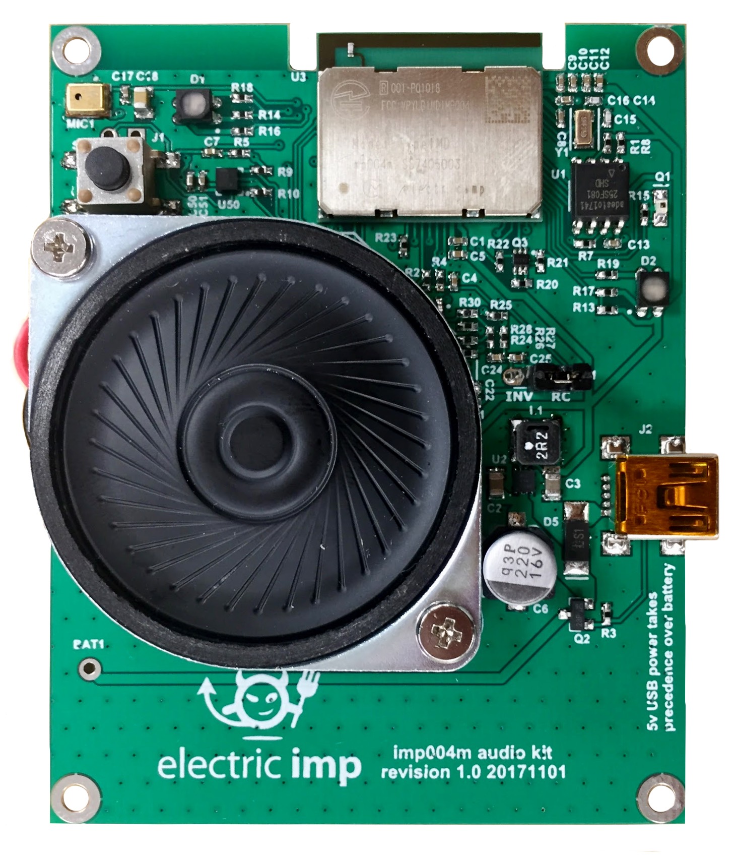
imp004m Audio Kit
The imp004m Audio Kit combines the imp004m module with a power supply, a 32kHz crystal (optional on imp044m designs) and required SPI flash. For audio input, it includes a Knowles SPK0415HM4H-B-7 MEMS microphone. Audio output is fed through an integrated filter circuit and a Richtek TPA2006D1DRBR 2.65W Class-D amplifier.

In addition to the Audio Kit’s sound processing functionality, the board also includes an RGB LED for application-controlled feedback, and an LIS2DH12TR three-axis accelerometer. It also provides Bluetooth LE support.
Set Up
To set up an imp004m Audio Kit, please see this page.
Hardware Details
Audio Input: Knowles SPK0415HM4H-B-7 Microphone
The SPK0415HM4H-B-7 MEMS microphone connects to the imp004m via the following GPIO pins:
| imp004m GPIO Pin | SPK0415HM4H-B-7 Pin | Notes |
|---|---|---|
| hardware.pinP | MIC_CLOCK | Fed with PWM output. Pin also connected to DFSDM clock input (Pin S) |
| hardware.pinQ | MIC_POWER | Drive high to power the microphone |
| hardware.pinR | MIC_DATA | Connected to DFSDM data input (pin R) |
You will use the microphone with the imp004m’s DFSDM (Digital Filter for Sigma Delta Modulation), which is used on the imp004m in place of other imps’ analog sampler. The DFSDM is accessed using the imp API object hardware.dfsdm. The hardware.dfsdm object expects an input on hardware.pinR and a clock signal on hardware.pinS. On the Audio Kit, these are connected to, respectively, MIC_DATA and MIC_CLOCK.
The Audio Kit’s input system can be set up with the following code stub:
local recordingProcessor = A_LAW_COMPRESS;
local dfsdmFilterOrder = 4;
local dfsdmDecRate = 64;
local dfsdmIntRate = 1;
local sampleRate = 15957;
local samplesPerBuffer = 1000;
local inputBufferSize = samplesPerBuffer * 2;
local buffers = [
  blob(inputBufferSize), blob(inputBufferSize), blob(inputBufferSize), blob(inputBufferSize),
  blob(inputBufferSize), blob(inputBufferSize), blob(inputBufferSize), blob(inputBufferSize)
];

function samplesReadyCallback(buffer, length) {
    if (buffer == null && length == 0) server.log("Sampling Overrun");

    if (length > 0) {
        // Process buffer...
    }
}

// Power up the the MIC
hardware.pinQ.configure(DIGITAL_OUT, 1);

// Set up the PWM-generated MIC clock signal. This is the output
// clock rate * DFSDM decimation rate * DFSDM integration rate.
// The duty cycle is 50 per cent
hardware.pinP.configure(PWM_OUT,
                        1.0 / (sampleRate * dfsdmDecRate * dfsdmIntRate),
                        0.5);

// Configure the imp044m Audio Kit’s DFSDM
hardware.dfsdm.configure(dfsdmFilterOrder,
                         dfsdmDecRate - 1,
                         dfsdmIntRate - 1,
                         offset,
                         0,
                         "RISING-EDGE",
                         buffers,
                         samplesReadyCallback,
                         recordingProcessor);
Audio Output: Richtek TPA2006D1DRBR Class-D Amplifier
The imp004m lacks a true fixed-frequency DAC, but it is nevertheless possible to use the imp API’s hardware.fixedfrequencydac object for audio output: it is emulated using PWM. The imp004m’s DAC emulation is output on pins K and D, which are specified using the object hardware.pwmpairKD when you configure hardware.fixedfrequencydac.
Pass the object hardware.pwmpairKD into hardware.fixedfrequencydac.configure()’s first parameter in place of the usual hardware.pin object. This configures pins K and D as digital outputs in PWM mode. Each pin outputs eight bits of a 16-bit sample at 96MHz: the most significant bits through pin K, the least through pin D. In this mode, all other hardware.fixedfrequencydac methods work as you would expect.
On the Audio Kit, pins D and K are connected to a filter circuit and then to the Richtek TPA2006D1DRBR, which drives the Audio Kit’s speaker terminals.
The following code example can be used to set up audio output on the Audio Kit:
local playbackProcessor = A_LAW_DECOMPRESS;
local sampleRate = 15957;
local samplesPerBuffer = 1000;
local inputBufferSize = samplesPerBuffer * 2;
local buffers = [blob(inputBufferSize), blob(inputBufferSize), blob(inputBufferSize), blob(inputBufferSize)];

function bufferEmptyCallback(buffer) {
    if (buffer == null) server.log("Playback Underrun");
}

// Configure the imp004m Audio Kit’s special FFDAC
hardware.fixedfrequencydac.configure(hardware.pwmpairKD,
                                     sampleRate,
                                     buffers,
                                     bufferEmptyCallback,
                                     playbackProcessor);
Bluetooth LE
The imp004m’s WiFi chip is the Cypress Semiconductor CYW43438 communication chip, which also supports Bluetooth 4.1. The CYW43438 Bluetooth unit is not connected to the imp004m’s MCU, but the CYW43438’s Bluetooth-specific pins are brought out to the imp004m pin-out to make them accessible to hardware designers who wish to make use of the module’s Bluetooth features in their products. They are connected to the imp004m Audio Kit as follows:
| imp004m GPIO Pin | CYW43438 Pin | Notes |
|---|---|---|
| hardware.pinE | LPO_IN | Drive low |
| hardware.pinF | BT_UART_RX | Access via hardware.uartFGJH |
| hardware.pinG | BT_UART_TX | Access via hardware.uartFGJH |
| hardware.pinJ | BT_REG_ON | Drive high to enable the Bluetooth LE sub-system |
The following code example will enable the Bluetooth LE on the imp004m Audio Kit:
// Set up Bluetooth on the imp004m Audio Kit
// Alias the relevant UART bus, LPO and power-on pins
bt_uart <- hardware.uartFGJH;
bt_lpo_in <- hardware.pinE;
bt_reg_on <- hardware.pinJ;

// Boot up Bluetooth: ground LPO_IN and set BT_REG_ON to High
bt_lpo_in.configure(DIGITAL_OUT, 0);
bt_reg_on.configure(DIGITAL_OUT, 1);
After making use of Bluetooth, you should set CYW43438 pins BT_REG_ON and LPO_IN low and if you wish to power down and fully disable the imp004m’s Bluetooth sub-system.
- For more detailed information on Bluetooth usage with the Audio Kit’s imp004m module, please see this guide.
LIS2DH12TR Accelerometer
The imp004m impExplorer Kit incorporates a LIS2DH12TR three-axis accelerometer. This I²C device is accessed via the non-default address 0x32 and is accessible via hardware.i2cMN: pin M is SDA, pin N is SCL. It is supported by Electric Imp’s LIS3DH code library.
The LIS2DH12TR’s interrupt trigger line is routed to hardware.pinW.
User LED
The Audio Kit’s user-controllable common anode RGB LED can be set using the following imp04m GPIO pins:
- hardware.pinA — Red
- hardware.pinB — Green
To drive the LED, drive either of these pins low, eg.
local state = true;

function loopLED() {
    imp.wakeup(0.5, loopLED);
    hardware.pinA.configure(DIGITAL_OUT, (state ? 0 : 1));
    hardware.pinB.configure(DIGITAL_OUT, (state ? 1 : 0));
    state = !state;
}

loopLED();