Design Battery Powered Applications
How To Design And Optimize Your Connected Product To Get The Best Battery Life
The Electric Imp Platform is great at delivering connectivity in battery-powered devices — in deep sleep, a typical imp draws just 4.5µA. Awake and connected to WiFi, an imp draws about 60-80mA on average, and less than 5mA on average in WiFi powersave mode. If you’re designing an imp-enabled device that will be battery-powered, the best place to start is to think about the full power story of your device.
Contents
Establish The Power Story
How Long Does The Device Need To Operate Between Charges?
Starting with your target battery life is a great way to help guide your decision-making process on the rest of the design.
Duty cycle is the key to battery life The best way to get long life out of batteries is to make your device spend as much time as possible in a low-power state. The less power used in this state and the more time you spend in it, the longer your battery will last. One of the most important parts of getting good battery life is writing your firmware specifically to spend as little time awake as possible.
There’s more battery life per charge to be had in primary-cell batteries than in rechargeable batteries If your use-case requires a lot of mileage out of a single charge, seriously consider using non-rechargeable primary cells. In addition to delivering more energy by cost or size, their lower self-discharge rate makes them a more effective solution for devices that need to work for a year or more on a single charge.
How Can Your Device Avoid Wasting Power When It Isn’t Needed?
Just like turning off the lights when you leave the room, a design with battery life in mind needs to be vigilant about wasted power.
Choose low-quiescent-current parts The quiescent current is the current a component will draw just to support itself. For instance, a linear regulator might support a 500mA load, but might still draw a quiescent current of 5µA when no load is present.
In designs where battery life is vital, a switching power supply is the best option for efficiency, quiescent current and supply current
Take advantage of parts with enable pins or low-current sleep modes It’s very helpful to be able to power-down entire portions of the device that are not in use, especially in devices that go to sleep often, or devices which will use different groups of components at different times.
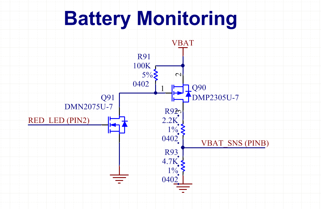
Gate power to portions of your circuit that don’t have a low-power mode This is a bit more of a brute-force strategy, but is important for things like passive resistive dividers used to measure battery voltage, eg. if you’re not actually reading the battery voltage, don’t drain power through the resistive divider.

This battery monitoring circuit is only switched on when the battery is being measured,
preventing wasted current through the resistive divider
What Should Happen When The Batteries Are Low?
When your battery power is spent, an imp will not be able to connect to the Internet to let the user know why it isn’t working. This can make for a very unpleasant user experience. If your device tracks its own battery voltage, you’ll be able to send a message to warn of a low-battery condition. Many of an imp’s pins can be used as an analog-to-digital converter (ADC) which can be used to read the battery voltage. Remember that an imp can only handle input voltages up to 3.3V (or only as high as VDD, if you’re running the imp at less than 3.3V); if your battery voltage might be higher, you’ll need to step it down.
Make Sure Your Power Supply Can Handle Running The WiFi Transmitter
When an imp powers on its WiFi transmitter, it will draw high current from the power supply in short bursts. These spikes may be as high as 250mA. It is extremely important to ensure that your battery and power supply can support this instantaneous load; if they can’t, you may brown-out or permanently damage your power supply.
imps cannot run on most coin-cell batteries. While these batteries may be rated at sufficient voltage and capacity to boot an imp, they are not rated to provide the instantaneous current required to run the WiFi transmitter. Attempting to do so can damage or destroy the battery. See the Battery Types table, below, for some other battery options and how to use them.
Get The Most Out Of The Available Power In Your Battery
Batteries have lower effective capacity when discharged at a higher rate. To help reduce the draw on the battery and maximize battery life, put a capacitor in parallel with the battery to reduce instantaneous draw and effective output impedance.
Select The Right Battery
Understanding Capacity
The capacity of a battery in milliamp-hours (mAh) doesn’t tell the whole story of how much energy is in a battery, nor does the voltage. The rated capacity in mAh is the number of hours a battery will last at a constant drain of 1mA. Note that a pair of AA alkaline batteries has the same rated capacity in mAh as a single alkaline AA battery: approximately 2700mAh. The difference is in the voltage the system power supply operates at. To roughly estimate the amount of energy in a battery, multiply its average voltage as it discharges by its rated capacity in mAh. Note that the battery’s voltage will change as it discharges.
For example, a AA lithium (LiFeS2) battery has a very flat discharge curve, and will hold approximately 1.5V as it discharges. This battery is rated at 3000mAh:
1.5 V x 3 A x 1 hour = 4.5 Watt hours
A pair of the same battery in series produces a total battery voltage of 3V:
3.0 V x 3 A x 1 hour = 9 Watt hours
Understanding Discharge Profiles
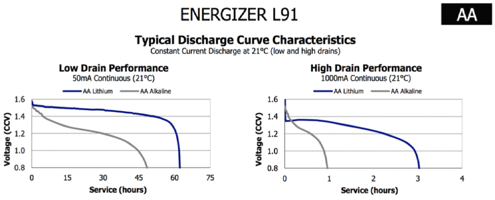
The voltage of a battery will change as it discharges. The slope and shape of the voltage versus time “discharge curve” of a battery depends on many factors, most notably battery chemistry and the average load the battery is under. Understanding the discharge profile of the battery chosen for your design is important because it will affect your assumptions about your power supply design. Will your battery voltage always be high enough to provide the needed headroom to operate your regulator? Will a fully-charged or even over-charged battery expose parts of your design to voltages outside of their rated limits and cause damage?

Effective Capacity vs. Discharge Rate for Energizer E91 (Alkaline) and L91 (Li/FeS2) Batteries

Li/FeS2 Batteries provide a much flatter discharge curve and can be used for many applications
in 2xAA configuration without an additional regulator
Commonly-Used Battery Types
| Battery Type | Voltage Range | Capacity (mAh) | Required Components | Pros | Cons |
|---|---|---|---|---|---|
| 4 x AA (Lala, Hannah) | 4.0V to 6.8V | Alkaline: 2700 NiMH: 2900 |
Buck | High capacity, lots of headroom, easy for user to replace | Bulky, replacing batteries increases cost of ownership |
| 4 x AAA | 4.0V to 6.8V | Alkaline: 1200 NiMH: 1000 |
Buck | Smaller than 4xAA, lots of headroom, easy for user to replace | Lower capacity, replacing batteries increases cost of ownership |
| 2 x AA Conventional (Nora) | 2.0V to 3.4V | Alkaline: 2700 NiMH: 2900 |
Boost | Good capacity, small form factor, easy for user to replace | Low capacity |
| 2 x AA Lithium | 2.0V to 3.4V | LiFeS2: 3000 | No additional components needed, small form factor, widely available | Same form factor as conventional AA batteries, very poor performance if replaced with Alkaline cells | |
| 9V | 5.0V to 9.0V | Alkaline: 310 to 565 | Buck | Convenient form factor, widely available | Low capacity |
| CR123A | 2.5V to 3.1V | LiMnO2: 1550 | Optional | No additional components needed, small form factor, widely available | Less capacity than other primary-cell options, less widely known by potential users than other primary cells (typically used in older cameras) |
| Li-Ion/LiPo | 3.2V to 4.2V | 500 - 3000 | Expensive. See Guide | Small or flexible form factor, rechargeable, decreases cost of ownership | Expensive, requires many additional components, less capacity per charge than most primary cells |
Set A Power Budget
Without a power budget, it’s very difficult to determine if your efforts to save power will allow your design to reach your target battery life. A power budget is the key to any power system design. This section shows how to develop a simple power budget, using the TempBug connected thermometer as an example application.
The TempBug is a simple Internet-connected thermometer. An imp001-oriented April breakout board is powered by a 9V Alkaline battery and connected to a 20kΩ resistive divider containing a 10kΩ fixed resistor and a 10kΩ NTC thermistor. By measuring the voltage in the center of the divider, the imp can determine the temperature. In this example, the imp wakes every 15 minutes, measures the temperature, uploads the measured value to its agent, and goes back to sleep.
Figure Out How Much Energy You Have To Spend
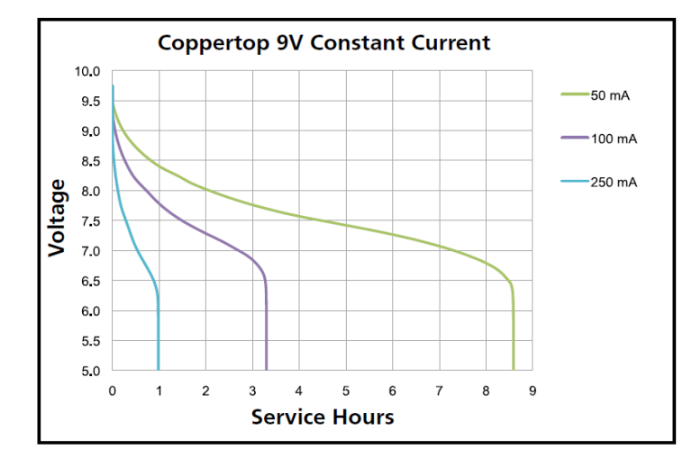
Examine the discharge curve for your battery and determine the average voltage the battery will hold while being discharged. Many battery manufacturers make datasheets available for their batteries, including Voltage versus Time graphs for discharge under several different loads. For example, Duracell helpfully provides a datasheet for its MN1604 9V Battery (PDF). This example will base power estimation on the 100mA constant current discharge graph provided in that datasheet:

Li/FeS2Voltage vs. Discharge Curve from Duracell MN1604 Datasheet
| Battery Type | Average Battery Voltage During Discharge (V) |
Battery Capacity (mAh) |
Battery Capacity (mWh) |
|---|---|---|---|
| Consult Datasheet | Consult Datasheet | Average Voltage x Capacity in mAh | |
| 9V Alkaline | 7.5 | 310 | 2325 |
Figure Out How Much Power The System Uses When It Is Awake
Determine the power consumption of each functional piece of the design. To find a part’s power consumption, multiply the operating voltage by the operating current, then multiply the result by the efficiency of the power supply used to provide the operating voltage. For example, in the TempBug, the imp001 will run at 3.3V and use about 80mA on average while transmitting. The imp’s 3.3V supply rail is provided by the DC/DC switching power supply, which operates at approximately 90 per cent efficiency:
| Part | Operating Voltage (V) |
Current Consumption (mA) |
Power Supply Efficiency (%) |
Power Consumption (mW) |
Notes |
|---|---|---|---|---|---|
| DC/DC Buck | 7.5 | 0.015 | 100 | 0.1125 | The DC/DC is supplied by the battery, so the efficiency of the power supply supplying this part is 100 per cent |
| ATSHA204A ID Chip | 3.3 | 0.00015 | 90 | 0.0006 | Used only by the imp during boot; the current number is from the ATSHA204A Datasheet (PDF). Consumption is essentially negligible |
| imp001 | 3.3 | 80 | 90 | 293.33 | Current consumption is worst-case average while transmitting; the imp will be transmitting most of the time when it is awake, so WiFi power-save does not apply (average power consumption when in WiFi power-save is approximately 10mA) |
| Thermistor Circuit | 3.3V | 0.000165 | 90 | 0.0006 | 20kΩ resistive load |
| Total | 293.45 | Power while awake in mW |
Repeat The Process Of Adding Up Power Consumption For When The Device Is Asleep
If your device has more states than ‘awake’ and ‘asleep’, you’ll need to perform this step for each state.
| Part | Operating Voltage (V) |
Current Consumption (mA) |
Power Supply Efficiency (%) |
Power Consumption (mW) |
Notes |
|---|---|---|---|---|---|
| DC/DC Buck | 7.5 | 0.015 | 100 | 0.1125 | |
| ATSHA204A ID Chip | 3.3 | 0.00015 | 90 | 0.0006 | |
| Electric Imp | 3.3 | 0.0045 | 90 | 0.01485 | |
| Thermistor Circuit | 3.3 | 0.000165 | 90 | 0 | Switched off when imp is asleep |
| Total | 0.128 | Power while asleep in mW |
Determine How Much Time Your Device Will Spend In Each State (The Duty Cycle)
Multiply the power consumption in mW for each state by the number of seconds per day the device spends in that state to find the total energy used per day in mWs. Divide by 3600 seconds per hour to find energy used per day in mWh. Divide by 24 hours to find the daily average power consumption in mW.
| Wake Interval (minutes) |
Time Awake (seconds) |
Time Awake / Day (seconds) |
Energy Used Per Day (mWh) |
Daily Average Power Consumption (mW) |
|---|---|---|---|---|
| Wake Power Consumption x Wake Time | ((86400 seconds/day) ÷ (Wake Interval in seconds + Wake Time in seconds)) x Wake Time in Seconds | ((Seconds Asleep x Sleep Power Consumption) + (Seconds Awake x Awake Power Consumption)) ÷ 3600 seconds/hour | Energy Used/Day ÷ 24 Hours/Day | |
| 15 | 5 | 477.35 | 42 | 1.75 |
Divide the capacity of the battery in mWh by the daily average power consumption in mW to get the battery life in hour, days
| Daily Average Power Consumption (mW) |
Battery Capacity (mWh) |
Battery Life (hours) |
Battery Life (Days) |
|---|---|---|---|
| 1.75 | 2325 | 1329.8 | 55.4 |
Conclusion
As we’ve seen above, the TempBug can expect just under two months’ battery life on 9V Alkaline battery with one five-second wake every 15 minutes. Tweaking the numbers used above, it becomes very quickly apparent that changing the duty cycle dramatically changes the battery life. The key to extending the life of a device like this is to think about how to use wakes and connections efficiently. For example, what happens to the above example if the imp wakes for just half a second every 15 minutes with WiFi off, taking the temperature and storing it to the imp’s nv storage, and then uploading the day’s results with just a single five-second connection every day?