imp005 Breakout
The imp005 breakout board provides basic life support for the imp005. The design includes power supply and GPIO breakout for the module, as well as the FCC/IC-approved dual-band (2.4/5GHz) antenna, an ethernet PHY and MagJack®, 32kHz crystal, and required QSPI flash.

Purchasing
This product is available to purchase at Mouser and Digikey.
Set up
To set up an imp005 Breakout Board, please see this page.
Pinout Chart
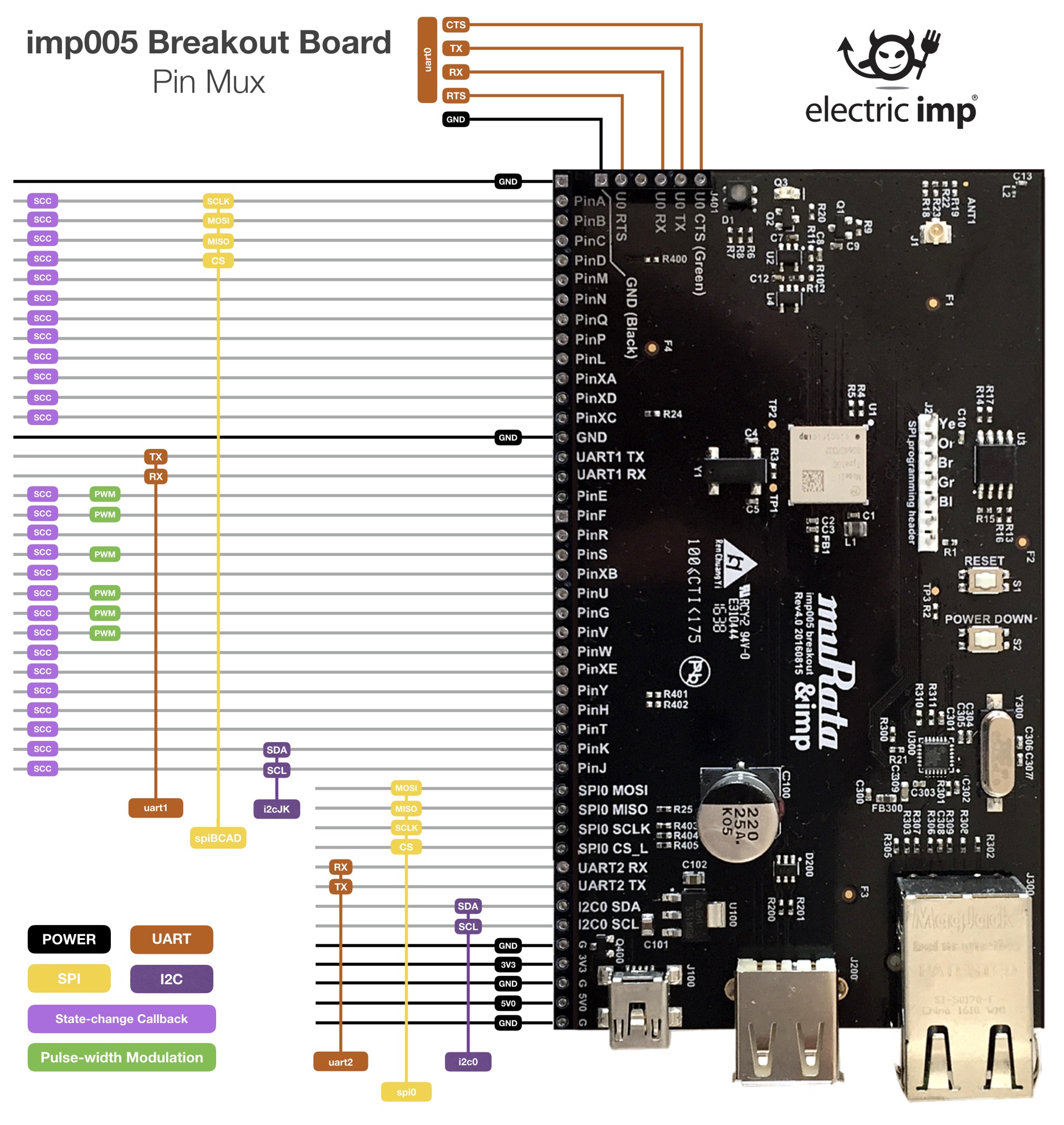
Click for larger version
Power
Power can be supplied using a USB Mini-B cable from a USB Charger or a standard USB Port, though the data lines are not connected to anything. Optionally, power can be provided through the 5V0 pin on the board edge. The USB mini-B connector should not be used if power is provided through the 5V0 pin.
imp005-breakout uses an LDO to provide 3.3v from the 5V0 input to both the imp005 and the USB PHY, and can accept a maximum input voltage of 6.0v.
The 5.0v input is also directly routed to the USB host (type A) connector on the board, to supply downstream USB peripherals being used with the board.
Signals
All of the usable I/O pins from imp005 are exposed on the 0.1-inch breakout. For descriptions of header pin functions, please see the imp005 pin mux. UART0 is broken out on the left board edge, and the pinout is compatible with an FTDI serial cable, allowing for easy connection when using UART0 for offline debugging.
The on-board antenna is a dual-band design, and if re-used correctly — see Design Hardware With The imp005 — allows you to reference Murata’s FCC/IC modular approval for the type 1GC module. An on-board u.FL connector is also provided if you wish to use an alternate antenna; to use this you need to remove R22 and stuff R23 to reroute the RF trace to the connector.
Ethernet support is provided by the Microchip LAN8720A RMII PHY, coupled with a Stewart Connector MagJack (RJ45 with integrated magnetics and LEDs) which provides the required isolation.
QSPI flash loading
The imp005 breakout is pre-programmed with an impOS™ image in the 64Mbit SPI flash. This OS connects to the Electric Imp Public impCloud™ if you wish to use the board with a Private impCloud™ instance, you need to reprogram the SPI flash with the encrypted image provided by Electric Imp technical support. To do this, fit a jumper linking J2.6 and J2.7 (this powers down the imp005 and ensures the SPI bus is tristated), then use a SPI programmer to load the new image.
There are many different options for programming; we use the FTDI C232HM DDHSL-0 cable. Next to J2 are color labels which identify which pin on the FTDI cable connects to which pin on the board (Ye = yellow, Or = orange, Br = brown, Gr = green, Bl = black); only five of the ten FTDI connections are used. Once connected and powered with the USB mini B input, use flashrom to write the image:
$ flashrom -n -p ft2232_spi:type=232H,port=A,divisor=8 -c "S25FL164K" -w image.rom
This process takes a couple of minutes. Once an image is loaded, the imp005 will securely upgrade to the latest impOS release when it next connects to its impCloud.
Project Files (Rev 6.0)
MagJack is a registered mark ® of Bel Fuse Inc.