Using WS2812 RGB LEDs
Integrate ‘NeoPixels’ Into Your Connected Product
NeoPixels™ are what component maker and seller Adafruit calls RGB (Red, Green, Blue) LEDs with integrated controllers, specifically the WS2811 and WS2812 parts produced by World Semi. They’re hugely popular. They are small enough to be supplied in semi-flexible strips or to be pre-mounted on a wide variety of circuit boards, yet smart enough to be individually addressable, giving you full control of the color of each NeoPixel in the group.
The NeoPixel combines the controller with three individual LEDs, one red, one green, the other blue. You supply the controller with the intensity values you want relevant LEDs set to, and it lights them accordingly, handling the pulse-width modulation duty cycles for you.
![]()
NeoPixels come in strips, on shaped boards and even individually
It’s worth stating up front: NeoPixels are delicate items, sensitive to both static electricity and to voltage spikes. Handle them with care. Adafruit has a wealth of guidance for working with NeoPixels, and you should read its ‘NeoPixel Überguide’ before adding them to your project. Here we’ll focus solely on how you integrate NeoPixels into an imp-based product.
Driving NeoPixels
NeoPixels are designed to be driven by a 5V supply. All imps are designed to operate at 3.3V. How can this voltage gap be bridged? There are a couple of options; which you choose will depend on the needs of your product.
The Basics
Most digital chips use a voltage level to represent the two digital states 1 and 0, or High and Low, respectively. Since a voltage is an analog value, chip makers specify two values, Voltage Input High and Voltage Input Low, abbreviated V_IH and V_IL, to tell you whether the chip will interpret a given voltage as High or Low. Basically, V_IH is the lowest voltage that is guaranteed to be recognized as a High. Likewise, V_IL is the highest voltage that will still be a 0.
Let’s look at an example. The WS2812b chip in a NeoPixel specs V_IH = 0.7 * VDD and V_IL = 0.3 * VDD. So if we set the power rail to 5V, then V_IH = 3.5V and V_IL = 1.5V. So any voltage 3.5V and up will be recognized as a 1 and any voltage below 1.5V will be a zero. What about in between? It could be either, so we want to make sure that our signal always swings below V_IL and above V_IH.
While the imp is nominally set to deliver 3.3V, its output won’t be exactly that but in the range VDD-0.4V. The actual value is called VOH. So even when running at 3.3V you could get as little as 2.9V out of an IO pin. In practice this doesn’t happen, and shouldn’t worry makers, but from an engineering standpoint it’s an important consideration.
5V and USB Power
Most 5V DC supplies and USB ports provide between 4.5V and 5.25V so we can use this to power the NeoPixels directly. If we check the V_IH for 5.25V, we find that we need our signal to rise to at least 3.68V, well above the 3.3V the imp typically outputs on the data line. This means that we will need to translate the signal up above 3.68V. You can buy discrete level-shifter chips such as the NXP’s 74AHCT125 or you can use any of a range of level-shifter boards which are easier to wire up. This guide uses one of the latter, Adafruit’s BSS138 four-channel I²C-safe bi-directional logic level converter. SparkFun’s Bi-Directional Logic Level Converter is another option.
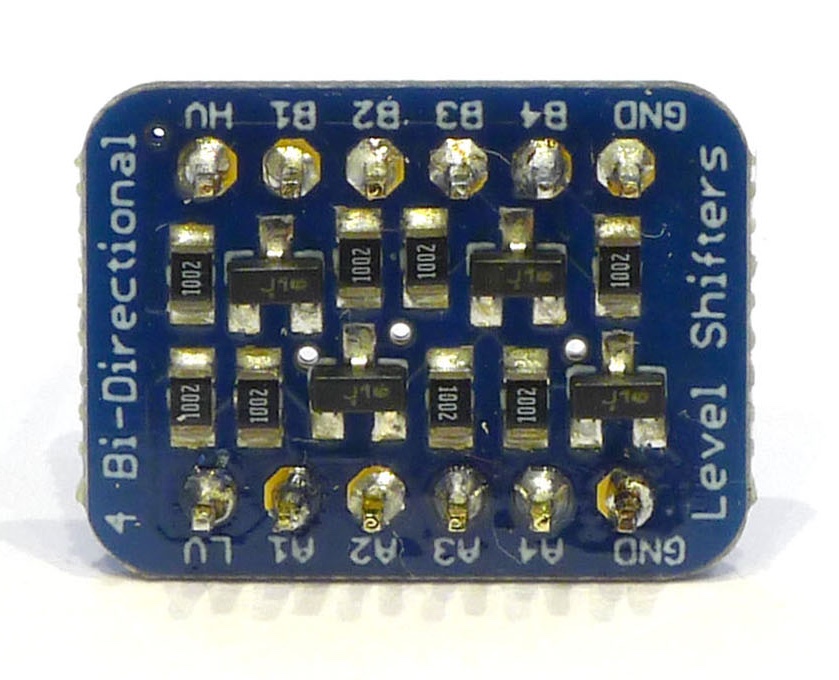
A level shifter with safely spans different voltage domains
Battery Power
Another option is to power your design with a Lithium Ion battery pack. These packs range in voltage from 4.2V when fully changed to 3.2V when empty. If we again check the V_IH level, we find that 4.2V * 0.7 = 2.94V. This means that we can drive the data line of the NeoPixels directly from an imp, no translation needed. Just be sure that when you are wiring it up that you don’t connect the battery directly to any of the imp’s IO or power pins.
The main downside to this approach is that the NeoPixels are only rated to run down to 3.5V (their V_IH value) so when your battery voltage gets below that they will be operating out of spec. You aren’t likely to damage anything but you may get unexpected behavior.
3V3 Power
It is possible to run a couple NeoPixels directly from an imp’s 3V3 supply, but it is not recommended. The WS2812 operating range is only good down to 3.5V so it may not be reliable and you may get changes in output color as the blue and green leds may not be able to turn on fully.
Current
Each NeoPixel requires up to 60mA of current to glow white at its brightest. Multiply that by the number of NeoPixels you have and divide by 1000 and you’ll calculate the maximum power requirement of your pixels, ie. the current your power source needs to be able to supply. So a 3A power supply should drive 50 NeoPixels comfortably.
In practice, the current draw is less: lower brightness levels and showing a colour rather than pure white requires less current. So does animating the pixels, because for a finite time the pixels will be turned off. Adafruit’s rule of thumb is to work to a third of the value calculated before.
Using NeoPixels
The imp’s SPI buses provide a good basis for emulating the one-wire protocol used to communicate with NeoPixels. This approach writes data to the bus in order to generate a waveform of the kind the NeoPixels expect to receive. One byte of SPI data represents a single NeoPixel bit. It’s a good idea to cache the byte-for-bit values ahead of time in an array: each entry in the array is an eight-byte blob which signals a value from 0 to 255 representing the intensity of a single color (of three) at a single NeoPixel (or however many you have connected). The values that go into each blob are 0xC0 for 0 and 0xF8 for 1.

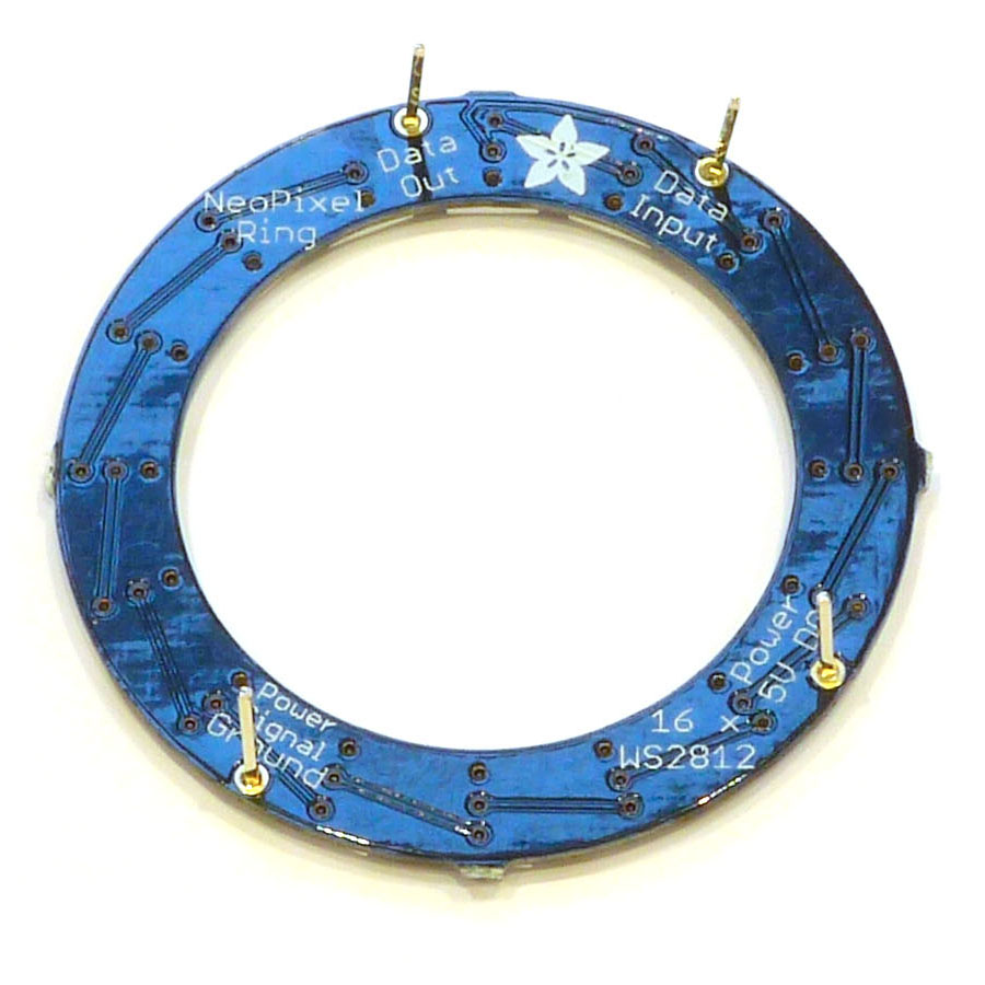
Test devices like a NeoPixel ring to find the first pixel in the line
For example, to set a NeoPixel white at maximum brightness, we need to send 0xFF for each of its three colors, red, green and blue. That requires sending 0xF8 over SPI for every bit that is a 1. Since all 24 bits in the combined three-color value are 1, we send 0xF8 via SPI 24 times, and that generates the waveform we need. To send a certain shade of green — in RGB, 0x7C, 0x90 and 0x0A — we need to send:
0xC0 0xF8 0xF8 0xF8 0xF8 0xF8 0xC0 0xC0 0xF8 0xC0 0xC0 0xF8
0xC0 0xC0 0xC0 0xC0 0xC0 0xC0 0xC0 0xC0 0xF8 0xC0 0xF8 0xC0
That is:
| Color | Hex Value | Decimal Value | Binary Value | SPI Bytes |
|---|---|---|---|---|
| Red | 0x7C | 124 | 0 1 1 1 1 1 0 0 | 0xC0 0xF8 0xF8 0xF8 0xF8 0xF8 0xC0 0xC0 |
| Green | 0x90 | 144 | 1 0 0 1 0 0 0 0 | 0xF8 0xC0 0xC0 0xF8 0xC0 0xC0 0xC0 0xC0 |
| Blue | 0x0A | 10 | 0 0 0 0 1 0 1 0 | 0xC0 0xC0 0xC0 0xC0 0xF8 0xC0 0xF8 0xC0 |
A quirk in NeoPixel design means that rather than accept color data in the RGB (red, green, blue) format, the WS2812s used GRB. Since everything else in the world works to RGB, it’s best to store your color data in that format and simply convert to GRB when assembling a frame. ‘Frame’ is the usual name for the bulk data used to set all of your NeoPixels to the color(s) you want. The frame then gets written in one go to the SPI bus.
If we have a frame blob with a size that’s 24 bytes times the number of NeoPixels — ie. 24 bytes per NeoPixel, eight bytes per color — we can set a single pixel’s color data into it by writing the 24 bytes calculated using the method above. If _frame is the blob, _bits the 256-element array of byte waveform blobs and color an array of three integers holding the red, green and blue values we want, we have:
function set(index, color) {
    // Check the passed parameters (note '_frameSize' is the number of pixels)
    assert(index >= 0 && index < _frameSize);
    assert(color[0] >= 0 && color[0] <= 255);
    assert(color[1] >= 0 && color[1] <= 255);
    assert(color[2] >= 0 && color[2] <= 255);

    // Put the blob read/write pointer the start of the correct
    // 24 bytes to reach the NeoPixel at pixelNumber. The 'b'
    // measures the offset from the beginning of the blob
    _frame.seek(pixelNumber * 24, 'b');

    // Red and Green are swapped, so convert RGB to GRB
    _frame.writeblob(_bits[color[1]]);   // Green
    _frame.writeblob(_bits[color[0]]);   // Red
    _frame.writeblob(_bits[color[2]]);   // Blue

    return this;
}
This function is called repeatedly, once for every NeoPixel. When we’ve constructed the complete frame, or if we want to send a single NeoPixel’s data immediately, we use:
function draw() {
    // '_spi' is the imp SPI bus to which the NeoPixels
    // are connected eg. hardware.spi257 in imp001
    _spi.write(_frame);
    return _this;
 }
However the line of NeoPixels is constructed — ring, strip or matrix — and however many pixels it contains, each is addressed by its position in a linear sequence. The first is 0, the second 1, the third 2 and so on. Addressing is indirect: you don’t pass a NeoPixel’s address via SPI. Instead the order of data in the frame provides the addressing: the first three color values are taken by the first NeoPixel in line, the second set of values by the next NeoPixel, the third by the third and so on. Take care with matrices of NeoPixels as it may not be immediately clear how the linear sequence of pixels has been laid out to form the grid.
![]()
NeoPixels are arranged linearly and are set by placing each one’s color data at the correct place in the frame
Wiring up NeoPixels
The NeoPixel protocol uses a single wire for data. All NeoPixel products have a Data In pin. You connect this to the imp, if necessary via a level shifter. Because we’re using SPI, we want the SPI output pin, MOSI (Master Out...). NeoPixels also have Data Out pin, which isn’t connected back to the imp. Rather it’s used to hook up the next NeoPixel product in sequence. This way you can build long chains of NeoPixels — or connect boards that each already contains a line of NeoPixels — and drive them all from a single pin on the imp. Don’t forget though that the more NeoPixels you add, the greater the peak current draw.
NeoPixel units need only be hooked up to 5V, GND and Data In
Data Out is used to connect the next ring, strip or matrix in the sequence
Because of the need to level-shift the signal from the imp, we connect our chosen MOSI pin (on the imp001, pin 7 with hardware.spi257, or pin 8 with hardware.spi189) to A1 on the shifter and the NeoPixel data line to shifter pin B1. Run a line from the imp’s 3V3 pin to the shifter’s LV pin and a line from VIN to HV on the shifter. The NeoPixel’s V+ feed also connects to VIN. Since we’re powering the imp001’s April development board via USB, VIN will be 5V. The NeoPixel’s GND pin and the two GND pins on the shifter can go to either of the April’s GND pins.
NeoPixel products will have 5V and GND pins at either end to help you chain them up. You can connect either end to your board; you don’t need to connect both. However, depending on the number of pixels you are driving, you may need to power them in batches to ensure they’re all uniformly driven and thus uniformly lit. Again, the Adafruit ‘NeoPixel Überguide’ has a lot of useful advice to help you with power wiring considerations.
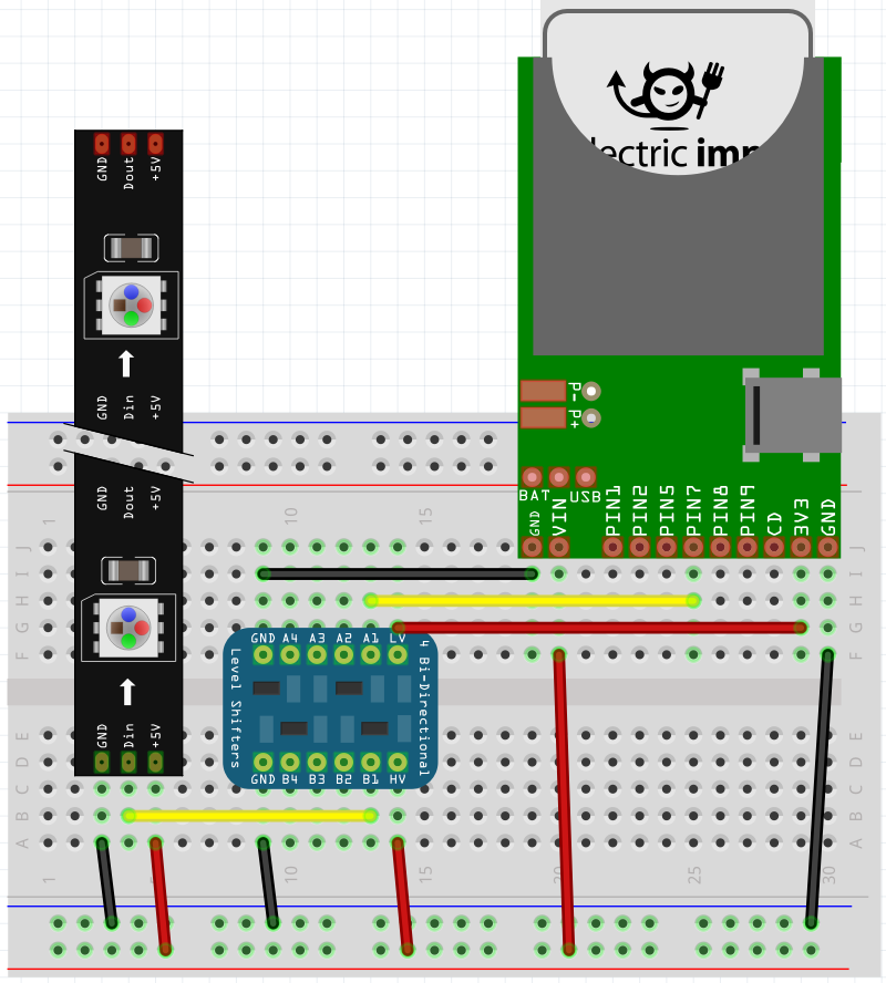
A typical imp-NeoPixel circuit with a level shifter for USB-fed 5V power
SPI Timing
The WS2812 protocol is timed, and the nearest available imp SPI clock speed is 7500kHz. This is readily available on the imp001. The imp003 ad imp004m don’t support SPI 7500kHz operation, but the imp004m can successfully drive WS2812s at 6000kHz. The imp003 should be set to 9000kHz, but requires some extra frame configuration work to be applied if it is to drive WS2812s. We recommend that you use the Electric Imp WS2182 library, which does this work for you.
We do not recommend using the imp005 with WS2812s. Unlike the imp001, imp002, imp003 and imp004m, the imp005 does not use DMA for SPI data transfers. Instead, each byte is written out individually, and this means there will always be a small gap between each byte. As a result, the LEDs may not work as expected and the performance of other operations, such as Agent/Device communications, are blocked when the Electric Imp WS2182 library’s draw() method is called.
Sample Code
Electric Imp’s WS2182 library provides all the code you need to drive one or more NeoPixels. It provides three public methods: to set the color of a single NeoPixel in a sequence, to set the color of a range of NeoPixels, and to write the stored color data out to the NeoPixels themselves over SPI.
* NeoPixel is a registered trademark of Adafruit Industries, LLC.