imp006 Breakout Board
The imp006 Breakout Board provides a full product evaluation, code development and product prototyping platform for the imp006 module. It includes not only comprehensive power management circuitry and a set of temperature, humidity and motion sensors, but also a user-controllable LED for visual feedback. In addition almost all of the imp006’s GPIO pins and standard buses are exposed on 0.1" headers.
The imp006 Breakout Board provides cellular connectivity through a Quectel BG96 chip cellular modem. It also includes both 802.11a/b/g/n/ac dual-band (2.4GHz and 5GHz) WiFi local-area networking and Bluetooth 5.0 personal-area networking thanks to the inclusion of a Murata LBEE5HY1MW wireless module.
It can be fitted into a New Age Enclosures case.

Board Versions
The latest version of the board, Rev. 4.0, makes a number of changes to the board’s layout. Rev. 4.0 boards will not exactly match the images of the board included here, which show an earlier version of the hardware. Some features are no longer required and have been removed. Such differences will be indicated in the relevant portions of the text below.
The imp006 Breakout Kit
The imp006 Breakout Board is currently available as a pre-built unit and sold as part of the imp006 Breakout Kit on the Electric Imp Store. The Kit is based on Revision 3.1 of the Board, and includes a Twilio Super SIM in MFF2 form to provide out-of-the-box cellular connectivity.
For details of the SIM’s capabilities and data allowance, please see the SIM section, below.
Device Activation
Please see our Getting Started Guide for step-by-step guidance on connecting a new board to the Electric Imp impCloud™ and adding it to your Electric Imp account.
Key imp006 Breakout Board Features
- Li-Ion/Li-Poly battery connector
- LTE Cat. M1/Cat. NB1 Cellular
- SIM slot
- 802.11a/b/g/n/ac WiFi
- Bluetooth 5.0
- Temperature and humidity sensor
- Motion sensor
- Grove Connectors
- mikroBUS
- GNSS
- GPIO Breakout
- User LED
imp006 Breakout Board Design Files
Power
The imp006 Breakout Board includes a mini USB port, a standard JST Li-Ion/Li-Poly battery connector (J5 on the board) and a two-pin header (J16) to which you can connect a non-rechargeable primary battery running at between 4 and 16V. The board will run without a battery attached when using the a power adaptor.
The power circuits are heavily optimized for each battery type and voltage range, allowing the breakout board to be used to accurately determine power usage in a final product design using the selected architecture.
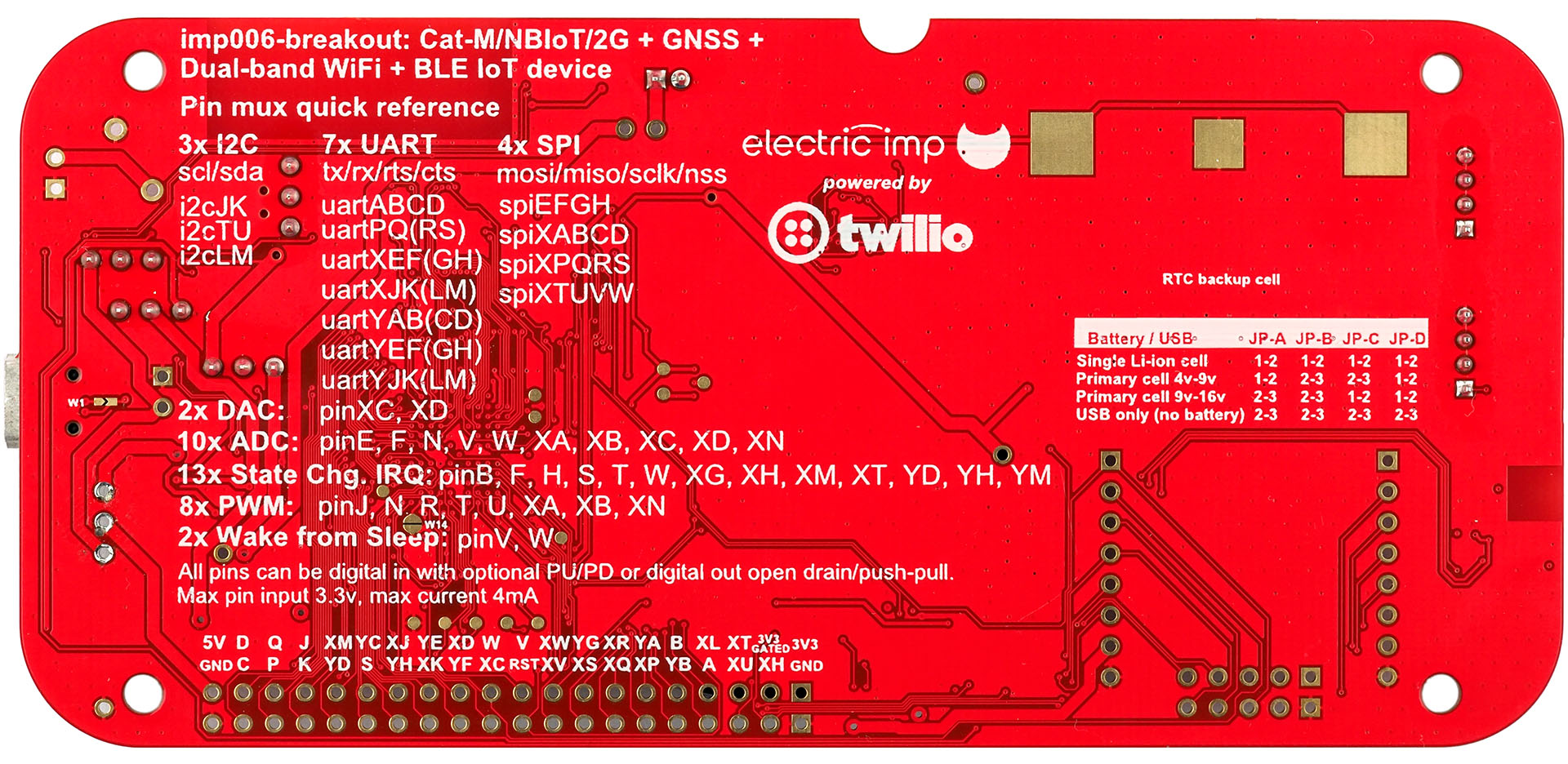
Depending on which of these power sources you select, you will need to set the jumpers (marked JP A through D) appropriately:
| Board Marker |
Single Li-Ion Rechargeable |
Primary Cell 4-9V |
Primary Cell 9-16V |
USB only (no battery) |
|---|---|---|---|---|
| JP-A | Position 1-2 | Position 1-2 | Position 2-3 | Position 2-3 |
| JP-B | Position 1-2 | Position 2-3 | Position 2-3 | Position 2-3 |
| JP-C | Position 1-2 | Position 2-3 | Position 1-2 | Position 2-3 |
| JP-D | Position 1-2 | Position 1-2 | Position 1-2 | Position 2-3 |
All of the jumpers will be initially set for USB power.
Jumper information:

Jumper JP-A
This is used to enable the primary buck, regardless of whether the MCU requires either radio (cellular or WiFi/BT) to be powered. Enable constant primary buck output by setting JP-A to position 2-3.
In position 1-2, the 3.8V rail is enabled when impOS demands either radio (cellular or WiFi/BT) be powered-up for communications.
In position 2-3, the primary buck for the 3.8V rail is constantly enabled. Reasons to enable the 3.8V rail constantly include:
- The primary buck supports a higher input voltage (up to 17V) than the high-efficiency buck regulator on the 3.3V rail (up to 10V). So if the board input voltage is greater than 10V then the 3.3V buck regulator should be supplied from the 3.8V rail as selected by JP-C. In this configuration, the 3.8V rail needs to remain enabled for the 3.3V buck at all times.
- Power to the BG96 must be maintained (eg. for GPS state preservation).
If the primary cell used is under 10v (and JP-C is hence set to position 2-3), the primary buck will only run when required.
Jumper JP-B
This determines how VMOD, the radio power supply for both cellular and WiFi/BT, is provided.
In position 1-2, VMOD is powered from from VSYS, the Li-Ion PMU system output. This should be selected when a Li-Ion rechargeable cell is powering the system.
In position 2-3, VMOD draws power from the 3V8 buck; use this setting when a primary battery pack is connected.
Jumper JP-C
This determines how 3V3, the imp MCU’s power supply, is sourced.
In position 1-2, 3V3 draws power from VMOD, which could be VSYS or the primary buck (see above). This should be selected when a Li-Ion cell is in use or a primary cell of >9V (the highest acceptable input for the 3V3 buck) is used.
In position 2-3, the 3V3 buck is fed directly from the primary cell. Only use this setting when the primary cell maximum voltage is under 10v (the maximum voltage of the high-efficiency buck regulator is 10V and exposure to voltages above this may damage it or reduce its lifespan).
Jumper JP-D
This is used to bypass PMU U1 from 5V0_IN to PRIMARY_IN, and so is intended only for battery-less operation, ie. the board is powered solely from the USB port.
In position 1-2, the 3V8 DCDC is fed from the primary battery.
In position 2-3, the 3V8 DCDC takes 5V0 USB as its input.
The primary battery’s voltage can be measured using imp006 pins YG and XD. To do so, connect the board solder bridges W9 and W12, and drive pinYG HIGH. PinXD’s input will now scale with the battery voltage.
LiIon Rechargeable Battery
A Maxim Integrated MAX17055 single-cell gas gauge IC and a Texas Instruments BQ24295 power management unit are included on the board. These components allow the board to manage an attached LiIon/LiPoly battery and monitor its charge level.
Charge/power management is automatic, so with a battery fitted the device will run the load from the input power directly, with any unused power within the input current limit being used to charge the battery. If the load is higher than the input current limit, power will be drawn from both the external input and the battery.
The default configuration for the charger is a 2A charge rate, assuming that the USB D+/D- lines advertise this. You can short W1 to enable a 3A current limit on the USB input if the supply you are using does not configure D+/D- for charger brick identify.
As such, a 2000mAh or larger 1S Li-Ion/Li-Poly battery should be used unless you are either using a limited power source, or reprogram the charge rate at startup. Libraries for these two components are linked at the bottom of this page, and they are accessed via the imp006’s hardware.i2cLM bus:
| IC | I²C Address |
|---|---|
| MAX17055 | 0x6C |
| BQ24295 | 0xD6 |
The imp006 Breakout Board includes an I²C isolator (U14) to ensure that the MAX17055 and BQ24295 do not load the hardware.i2cLM bus when a primary battery is being used in place of a LiIon power source.
Solder board bridge W3 if you wish to connect the BQ24295’s IRQ pin to the imp006’s XM pin.
Solder board bridge W10 if you wish to allow the imp006’s YC pin to control the BQ24295’s 5V0 boost output.
The USB voltage and identified current limit can be requested from the BQ24295.
The bridges are marked below:

A suitable battery can be obtained from a wide variety of online resellers. The charger library defaults are for a 2Ah battery — this battery matches the charger IC defaults.
Wireless Connectivity
Cellular
The imp006 Breakout Board provides LTE Cat. M1 and Cat. NB1 (NB-IoT) cellular connectivity using the Quectel BG96 cellular modem. It can fall back to quad band 2G as required and as available in the territory in which it is operating.
Please see the SIM section for information on NB-IoT usage.
The BG96 connects to the imp006 via a dedicated USB channel and a UART. Connectivity to the impCloud is managed by impOS, but can be managed by the application.
Network Activity
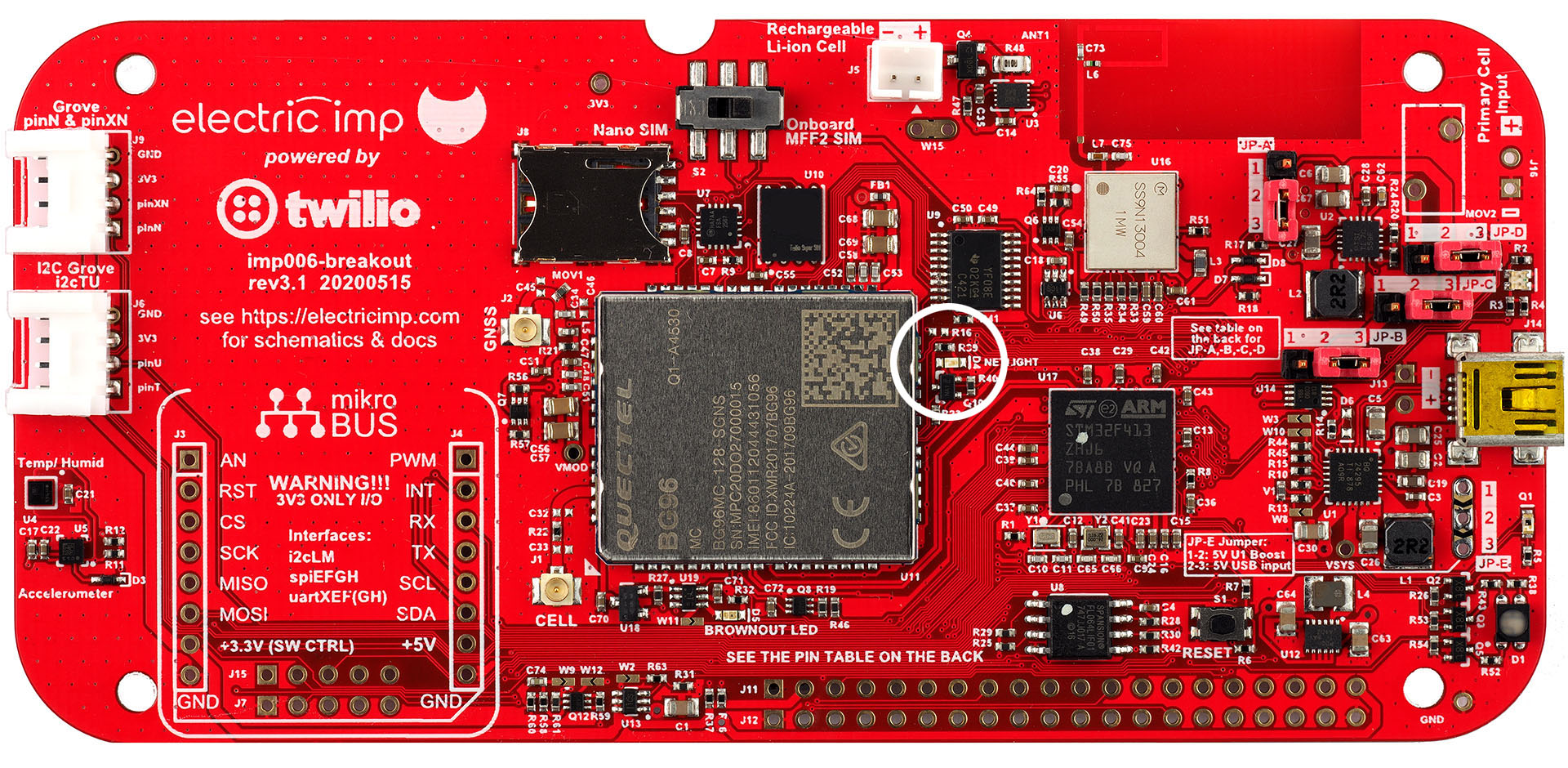
An LED (D4) on the board provides network status information:
- Short on, long off flash — Searching for network.
- Long on, short off flash — Registered on network.
- Fast blink — Data transfer.
The LED is marked below:
Radio Brownout Detect
The board includes a circuit which detects when the radio is powered and radio power source drops below 3.3V. If this happens, LED D5 is illuminated, indicating a possible supply issue. This usually indicates insufficient current available, especially on 2G networks. This circuit is provided to help diagnose issues with supplies feeding the breakout board during development, and generally would not be used on a production device.
If solder bridge W11 is connected then the imp006 can monitor radio power status by reading pin XL. W11 is marked in the image below:

The indication is cleared by a reset.
SIM
Early versions of the imp006 Breakout Board incorporated a Twilio Super SIM in MFF2 form. This component is not included on Rev. 4.0 of the board, and the Nano SIM receptacle has been placed at the edge of the board for easy access. The SIM switch has also been omitted from the new board:

A Super SIM card is included with imp006 Breakout Boards sold through the Electric Imp Store.
To make use of the bundled Super SIM, you will need a Twilio Account. Please sign up for a free trial account now if you don’t have one. You will then need to register the SIM with your account. To do so, visit the SIM registration page in the Twilio Console and enter the registration code shown on the Super SIM card:

Lastly, you need to set up your SIM: the networks it can access, its data limits and so forth. Please see this Twilio Super SIM setup guide for details.
Super SIM enables Cat-M1 and fallback 2G (where this exists). It does not support NB-IoT, but you can connect to available NB-IoT networks using a Twilio Narrowband SIM (US only).
Warning The 4FF SIM slot allows SIMs to be inserted either way round, but the Breakout Board expects SIMs to be inserted notched/narrow end first. Please ensure that you insert your SIM correctly:
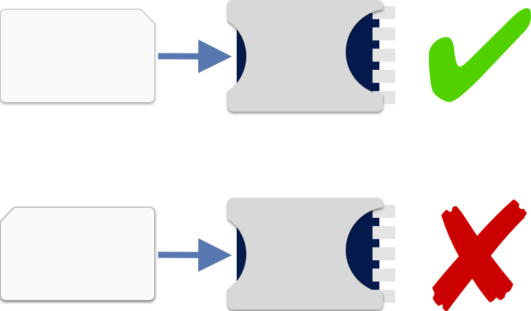
impOS only supports Twilio SIMs, so you will not be able to use a SIM from a carrier or another supplier.
For Rev 3.1 baords and under, if you add a SIM card to the board, you must slide the SIM selection switch to the left, toward the label Nano SIM, for it to be used by the modem. To use the integrated Twilio Super SIM, make sure the switch is set to the right, toward the label Onboard MFF2 SIM. As noted above, this switch is not present on Rev. 4.0 of the board.

Further Information
- See Twilio’s How to Determine Good Cellular Signal Strength to learn more about measuring signal quality using the BG96.
- Known impOS Issues With Twilio Super SIM.
Connector
The imp006 Breakout Board design incorporates a u.FL connector to which a suitable cellular antenna should be connected. Such an antenna is included with the imp006 Breakout Kit, the pre-assembled version of the board.
Please note that the u.FL connector is delicate and should not be overly stressed. Nor should you repeatedly fit and remove the antenna: the u.FL connector is rated to just 30 insertions.

Further Information
WiFi
The imp006 module supports the connection of an external communications unit through a dedicated SDIO bus. The imp006 Breakout Board uses this to provide 802.11a/b/g/n/ac WiFi through a Murata LBEE5HY1MW radio module. This incorporates a single antenna to deliver peak throughput of up to 433Mb/s.
The board’s WiFi interface is controlled generically through impOS. It may be used as the board’s primary connection to the impCloud, as a secondary interface backing up the cellular connection, or as an interface for local networking using the User Datagram Protocol (UDP). The imp006 can use WiFi to connect to the impCloud while also connecting to local devices using UDP — these are not mutually exclusive roles.
WiFi only draws power when your application requests a WiFi connection; it draws <1μA when shut down due to the power gating arrangement, which is controlled automatically by impOS.
Further Information
Bluetooth
The Murata LBEE5HY1MW radio module incorporates Bluetooth 5.0, connected to the imp006 via a dedicated UART which is not exposed to Squirrel. This functionality can be accessed through impOS’ hardware.bluetooth API.
Calling hardware.bluetooth.open() on the imp006 requires no arguments (an exception will be thrown if any are passed). Therefore you do not need to provide a UART, modem firmware or optional settings as you do with the imp004m:
// BLE on imp006
ble <- hardware.bluetooth.open();
Additionally, you do not need to assign imp006 GPIO pins to modem LPO_IN and REG_ON, which you may expect to do if you have worked with Bluetooth on the imp004m. You are not able to apply an alternative MAC address, or HCI baud rate.
BT only draws power when your application opens the hardware.bluetooth object; it draws <1μA when shut down due to the power gating arrangement, which is controlled automatically by impOS.
- For a more in-depth guide to Bluetooth on the imp006, please see How To Use Bluetooth With The imp006.
Sensors
The imp006 Breakout Board includes the following sensors:
| Sensor | Measured Quantity | I²C Address (8-bit) | Library | Datasheet | Example |
|---|---|---|---|---|---|
| HTS221 | Temperature, humidity | 0xBE | HTS221.device.lib.nut | Link | Sample 1 Sample 2 |
| LIS2DH12 | Motion in three axes | 0x32* | LIS3DH.class.nut | Link | Sample 3 |
* This is not the sensor’s default I²C address, so you will need to add its address into the class constructor of its Electric Imp library.

All of the sensors can be easily accessed in application code using the Electric Imp libraries named in the table above. Click the library links for the latest version.
Note The LIS2DH12 intentionally makes use of the LIS3DH library as these two devices are functionally equivalent. These sensors are accessed via the imp006’s hardware.i2cLM bus.
Note The board’s built-in sensors are on the same I²C bus as the MikroBUS connector, so please check for I²C address clash if you are using more than one of these peripherals.
Peripheral Connectivity
Grove Connectors
The imp006 Breakout Board incorporates two Grove System-compatible headers, each of which connects to a four-wire cable with two data wires (yellow and white) plus 3V3 (red) and GND (black). For information about the Grove System, please see the Seeed Wiki.
Power to both Grove headers is gated by pin XU, which must be set HIGH to power Grove peripherals. Alternatively, solder bridge W2 on the board to force Grove power on.
See the guide Using Grove System Components for assistance with connecting Grove peripherals to the imp006.
See this code sample and this code sample for examples of adding Grove peripherals to the Kit.
Analog and Digital
One header, marked J9, is intended for Grove Analog and/or Grove Digital peripherals: its A0/D0 (yellow) and A1/D1 (white) lines are connected, respectively, to the imp006’s pins N and XN.
I²C
The other header, J6, can be used to drive a variety of Grove-compatible devices which operate over I²C. When configured for I²C, devices are accessed using the imp006’s hardware.i2cTU bus. The yellow wire provides the clock line; the white wire the data line. Only 3V3 I²C devices are supported.
mikroBUS
The imp006 Breakout Board provides an optional header pins to allow you to install a mikroBUS connector. Such a connector allows you to fit Click boards (not included) from MikroElectronica. Click is an ecosystem of available modules which can be used to add a wide variety of peripherals.
SPI, UART and I²C interfaces are available through the mikroBUS header, and additional Click control signals are connected to the imp006 GPIO and can be controlled via firmware. 3.3V power to the Click board is gated by pin XU, which must be set HIGH to enable the power supply. The supply is gated to allow low power sleeping even with high current Click boards fitted. Solder bridge W2 on the board to force mikroBUS power on.
Note that though 5V is available on this connector, all the I/Os are 3.3V only. Please ensure that the Clicks you fit are 3.3V compatible.
The Click 5V line power is controlled via jumper JP-E. Set this to position 2-3 to drive the Click 5V pin from the Breakout Board’s USB input. Set JP-E to position 1-2 to drive the Click 5V pin from the Breakout Board’s PMU (marked ‘U1’), or to drive the Breakout Board from a suitable Click. The PMU can only be used as a power source if a 3.7V Li-Ion cell is connected to the Board and it is not charging.
Note If you are using JP-E position 1-2 to boost from Li-Ion to 5V, you need to drive the OTG pin on the PMU high. You do this by soldering link W10 and driving hardware.pinYC high (see the schematics). You will also need to ensure that REG01 bit 5 is high, though it is by default.
| Click Pin No. | Click Name | Description | imp006 Pin |
|---|---|---|---|
| 1 | AN | Analog | V |
| 2 | RST | Reset | YH |
| 3 | CS | SPI Chip Select | H |
| 4 | SCLK | SPI Clock | G |
| 5 | CIPO | SPI Master In | F |
| 6 | COPI | SPI Master Out | E |
| 7 | 3V3 | ||
| 8 | GND | ||
| 9 | GND | ||
| 10 | 5V0 | ||
| 11 | SDA | I2C Data | M |
| 12 | SCL | I2C Clock | L |
| 13 | TX | UART TX (to Click) | XE |
| 14 | RX | UART RX (from Click) | XF |
| 15 | INT | Hardware interrupt | W |
| 16 | PWM | Pulse Width Modulation signal to Click | XG |
Note 1 The mikroBUS connector is connected to the same I²C bus as the Breakout Board’s integrated sensors, so please check for I²C address clash if you are using more than one of these peripherals.
Note 2 CIPO and COPI were previously MISO and MISO, respectively.
The imp006 Breakout Board provides two further headers adjacent to the mikroBUS headers. These extra headers, J7 and J15, are not required by the mikroBUS, but are included to facilitate easy access to a number of the imp0006’s GPIO pins from connected Clicks.
| J7 Pin No. | imp006 Pin |
|---|---|
| 1 | GND |
| 2 | XH |
| 3 | XG |
| 4 | XF |
| 5 | XE |
| J15 Pin No. | imp006 Pin |
|---|---|
| 1 | 3V3 |
| 2 | YM |
| 3 | YL |
| 4 | YK |
| 5 | YJ |
GNSS
The Quectel BG96 module also supports GNSS (Global Navigation Satellite System) operation using all of the major satellite-based location detection systems, including GPS, Galileo, Glonass and BDS.

We have a Squirrel library which can provide your application with access to GPS location data retrieved from the BG96. The BG96 will need to be connected to an external antenna for GNSS operation; the imp006 Breakout Board design incorporates a u.FL connector to which a suitable GNSS antenna should be connected. An active antenna is included with the imp006 Breakout Kit, the pre-assembled version of the board.
Please note that the u.FL connector is delicate and should not be overly stressed. Nor should you repeatedly fit and remove the antenna: the u.FL connector is rated to just 30 insertions.
GPIO Breakout
The imp006 Breakout Board’s GPIO pins are broken out to two rows of header pins, J11 and J12. The GPIO to which each pin is connected is printed on the reverse of the board. Please see the imp006 Pin Mux page for information on all of the many GPIO pins and standard buses made available by the module and exposed via the Breakout Board.
Alternative UART Breakout
In addition to the primary GPIO breakout, headers J7 and J15 break out hardware.uartXEFG and hardware.uartYJKLM, respectively. These may be used for any UART applications, but are primarily intended for custom mikroBUS Click modules.
Miscellaneous Hardware
User LED
The imp006 Breakout Board’s user-controllable LED can display 7 colors with static pin drive (compatible with the imp shallow sleep modes, so the imp can drop into shallow sleep with the LED lit) and any number of colors when the pins are set as PWM (not compatible with the imp shallow sleep mode).
It is controlled on pins R (red), XA (green) and XB (blue). Set any or all of these pins HIGH to enable the relevant color, or use PWM_OUT as appropriate.
Reset Button
On versions of the imp006 Breakout Board up to and including 3.1, the RESET button is located to the right of the board, above the GPIO pin array.
Rev. 4.0 of the board relocates the RESET button to the upper edge of the board, alongside the SIM receptacle.
Accessories
The imp006 Breakout Board has been designed to fit in the following enclosures:
Additional Programming Resources
Power Management Libraries
GNSS Library
Multi-interface Networking
UDP Local Networking
Bluetooth
Grove Connectors
Sample Code
- A visual thermometer
- A visual range-finder
- Temperature and humidity sensors
- Accelerometer and temperature/humidity sensors