Using Segment and Matrix LEDs
Add Simple Digital Readouts To Your Connected Product
LED displays are a great basis for simple data readouts that you can add to your product, whether you need to present a numeric value, such as a temperature reading, or an icon — a weather forecast, say. Fortunately, there are not only a great many LED display units available to developers, but component suppliers often provide them with breakout boards to simplify the process of hooking the LED panels up to a development imp.
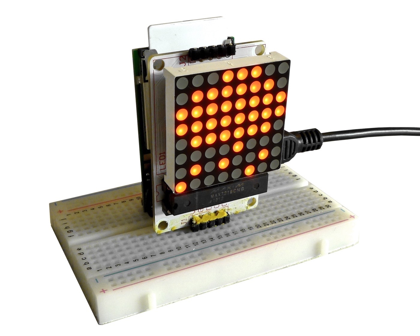
An 8x8 LED matrix display
These boards feature a controller chip with which an imp can communicate via one of its I²C or SPI buses. I²C has the particular advantage of tying up only two of the imp’s pins; a ‘raw’ 8 x 8 matrix LED unit has 16 pins, by comparison. Because I²C identifies each device on the bus with a unique address, it is also a good choice when you want to add more than one peripheral — display plus temperature sensor, say — from those two pins. SPI requires three wires for the bus plus a fourth for the Chip Select line.
Although these backpack-equipped LED displays are primarily intended for the Arduino platform, the source code their suppliers provide is usually easy to convert, especially if you also have a copy of the controller chip’s datasheet to hand. When one supplier finds a chip they like, the usually stick with it so that it ends up as the basis for a range of display products. So you can generally re-use code you’ve written for one display based on that controller with another.
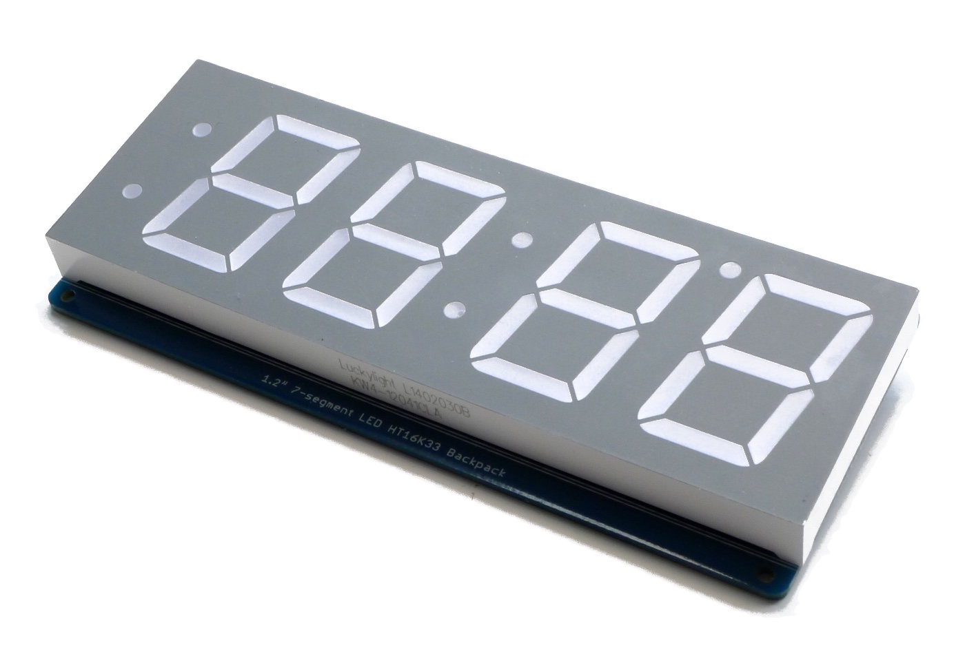
A large four-digit, seven-segment LED segment display
LED Display Types
LED displays fall into two basic types: segment and matrix.
The former are classic ‘calculator’ displays, designed to show a sequence of numbers generated by enabling or disabling any of the seven LED segments from which each digit is constructed. Groups of digits may come separated by colons and/or decimal points. You tell the display which segments to light up for each digit. You’re not limited to numbers; you can form letters out of the segments too. But you will often have to mix upper and lower case letters (and not use others at all) to avoid ambiguity: is it a zero being shown or a capital d, for instance?
You can avoid this by using alphanumeric displays. These have a greater number of segments per character, usually 14, which add diagonal lines to the vertical and horizontal ones to give you the flexibility to present a greater range of character glyphs than seven-segment displays can.
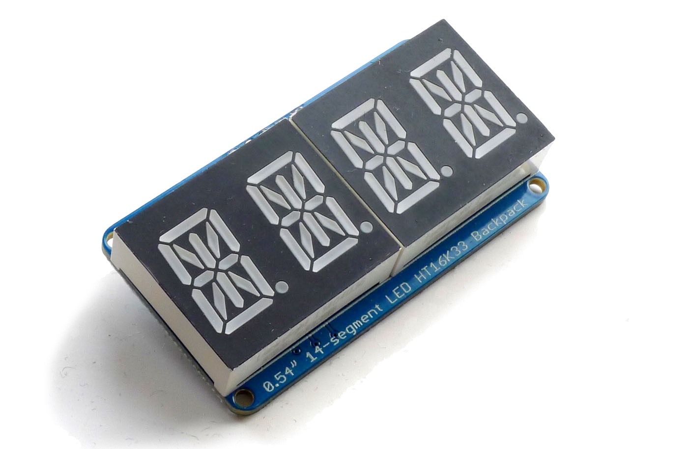
An alphanumeric segment LED display
Matrix displays, meanwhile, are straightforward grids of square or circular pixels. This makes them well suited to display icons and other basic graphics, but they can also be used to form alphanumeric characters. A downside is that you’ll need one of these for every character you want to display at once, though by scrolling characters and graphics across the display, you can maximize the amount of information you can display in a small space.
LED Controllers
There are a huge number of LED controllers on the market, but one of the most commonly used is the Holtek HT16K33. It’s the basis for most of Adafruit’s LED displays, for example. Another is the Maxim Integrated MAX7219. Both chips were designed to drive regular matrix displays, but since a segment display is essentially a matrix too, albeit ones with irregular pixels, these controllers are also often found on segment LED breakout boards.
Communicating With The Chip
Controller chips typically include memory in which the data for each segment of each digit, or each pixel of each row is stored and then used to turn the respective segments and pixels on and off. This memory is usually addressable directly via I²C, so you just need to put the data on the bus and the controller does the rest.
An 8 x 8 matrix, for example, might require eight 8-bit integer values to define the image it displays, each bit controlling a single pixel. The display might require larger values if it contains multi-color LEDs, for which a simple binary ‘on or off’ value isn’t sufficient; you need to express a color-choice too. The HT16K33, for example, uses 16-bit values, but for monochrome LEDs the upper eight bits (which are sent after the lower eight bits) can all be cleared to zero.
That said, much depends on how a given display’s component LEDs, be they segments or pixels, are arranged. So you’ll need to examine source code and/or the datasheet to help you understand their order, which may not necessarily match how they appear to have been placed on the breakout board.
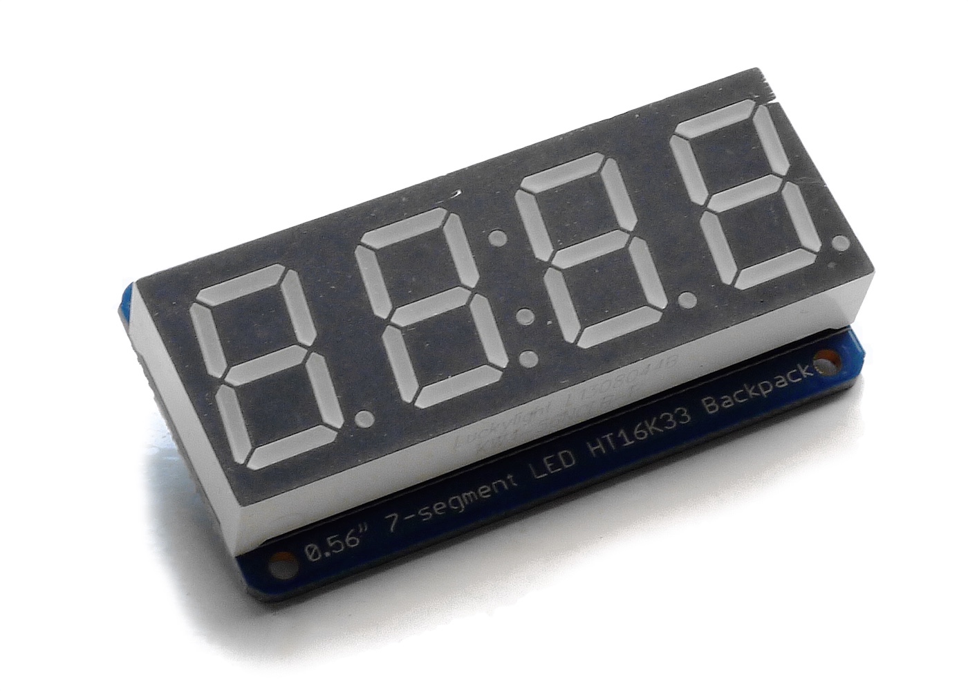
A numeric LED segment display
For example, Adafruit’s bi-color 24-bar graph LED uses the HT16K33 to drive the 48 LEDs on the board. Two LEDs, one red, the other green, sit behind each bar; you can light both to make a third color, amber. The LEDs aren’t, however, arranged in simple numeric sequence, one byte per LED, but arranged in groups of bits. To address a specific bar, your code needs to decode that arrangement. Our sample code will help (see below).
Seven-segment LEDs are usually organized by character, left to right, with an eight-bit value for each: the first seven bits define the character segments, the eighth a decimal point following the number. Colon separators — used for time displays — are often defined as single character: you just need set bit 7 to show it. Again, even though two different displays are based on the same chip and are both segment-based, their LEDs may be organized in different ways, so pay attention to the source code.
LED brightness is generally controlled by an on-board pulse-width modulator; you write a value which determines the duty cycle.
I²C Addressing
The HT16K33 is designed to operate over an I²C bus. It supports a range of I²C addresses, and these are set by shorting a number of the chips pins. On breakout boards, this is usually achieved by bridging one or more conductor pads with solder. By supporting multiple addresses, the HT16K33 allows you to assemble several displays to create a larger panel, though you interact with each display individually. Each display is uniquely addressed, so your code will need to know which display on which to write a given character.
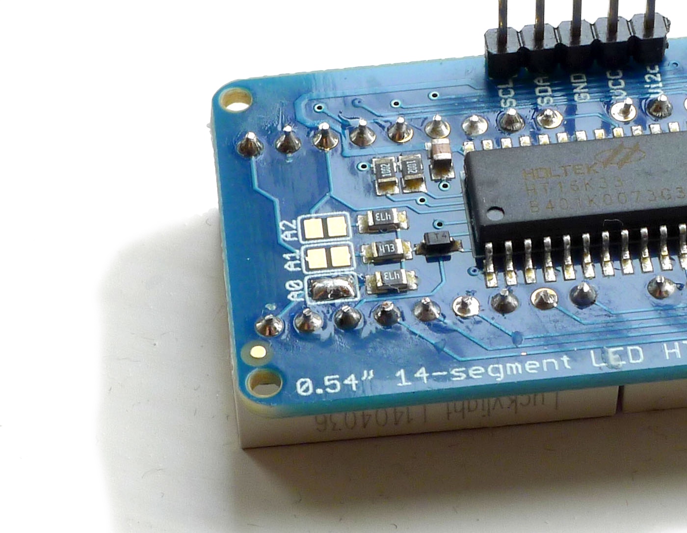
Setting the I²C address
Beyond I²C
Not all displays use I²C. Some use SPI or variants of it; the MAX7219 does, for instance. Again, which bus you need will depend on the display product you’re using.
Usage
Segment Displays
Adafruit offers an number of LED segment displays, all based on the HT16K33 controller and which connect to the imp via I²C. Among them are:
Embedded Labs offers an 8-digit, 7-segment LED, but this is based on the MAX7219:
The links go to the red versions, but other colors are available too. They are also those offered with I²C breakout boards. You can also buy the LED displays on their own, but these require more complex wiring and so are not covered in this Guide.
Characters are assembled by setting the bits that correspond to each segment. For the Adafruit 0.56” segment displays, which are particularly handy for clock and thermometer read-outs, bit-to-segment mapping runs clockwise from the top around the outside of the matrix; the inner segment is bit 6:
  0
  _
5 |   | 1
  |   |
  - <----- 6
4 |   | 2
  | _ |

  3
Bit 7 sets the period that follows each digit. On the 1.2” display, the single period, between characters 2 and 3 (read left to right, starting at character 0) is handled separately, as are the colons. Both displays organise characters in memory this way:
| Character | LSB Address | MSB Address |
|---|---|---|
| 0 | 0x00 | 0x01 |
| 1 | 0x02 | 0x03 |
| Colon | 0x04 | 0x05 |
| 2 | 0x06 | 0x07 |
| 3 | 0x08 | 0x09 |
All of the 1.2” colons and period are set or by placing OR’d constants in the colon memory. The 0.56” display’s single colon is set or unset by writing 0xFF for on or 0x00 for off to 0x04.
The HT16K33 stores 16-bit values and these are written to I²C as two 8-bit numbers, least significant byte first. So each digit value you send needs to be followed by 0x00. To set row 0 to the number 9, then, you’d use the following code:
hardware.i2c89(address, "\x00" + "\x6F" + "\x00");
The first value after the I²C address is the address of the row we want: 0x00, according to the datasheet. The second is the value that defines the character ‘9’, ie. bits 0 through 6 all set except for bit 4. The third value is the remainder of the 16-bit value the controller expects. "\x" tells Squirrel that the characters that follow should be converted into an unsigned 8-bit integer value.
The 14-segment display works the same way, but uses bits 8 through 14 of the 16-bit value for the extra segments and period, here broken out for clarity:
  0              9
  _
5 |   | 1      8 \ | / 10
  |   |           \|/
         6 -- -- 7
4 |   | 2         /|\
  | _ |       11 / | \ 13      . 14

  3              12
To write an ‘X’ at the first character, you’d use:
hardware.i2c89(address, "\x00" + "\xC0" + "\x2D");
In each case, it’s a good idea to calculate character values ahead of time and store them in an array in your Squirrel code so you can access the easily whenever you need to.
You can write display values immediately or add them to a buffer array from which they can later be read and written all in one go. This applies to the matrix displays too, but this time the values you send define the overall pattern of lit and unlit pixels. Again, it’s a good idea to define key characters — numbers, letters, symbols, icons etc — ahead of time in an array. Here each character could itself be an array of eight 8-bit values, all placed in a character set array.
Matrix Displays
Here are three typical Adafruit matrix displays, all based on the HT16K33 controller:
Adafruit’s matrix displays have a quirk: bits 7 through 0 of each line’s 8-bit value need to be sent in reverse order through 7, but before the result is sent it needs to be rotated to the right: what was bit 0 becomes bit 7.
In other respects, they are straightforward: send the eight 8-bit values to the display in row order via I²C. MAX7219-based matrix displays, such as LinkSprite’s LED Matrix Kit, are easier to use — there’s no extra bit manipulation to make. The quid pro quo is that the MAX7219 doesn’t support I²C but SPI.
In the case of the LED Matrix Kit, you can just hook up the board’s DIN (Data in), CLK (clock) and CS (chip select) to any imp pins, or use an SPI bus with the MOSI pin connected to DIN, SCLK to CLK and a third, GPIO pin for CS.
Either way, to write to the controller, you set CS low, send over the address of controller’s register you’re targeting, send the data to be written to that register and finally set CS high. Here are two functions that enable this:
function write(regAddress, value) {
    // Writes data to the LED in the MAX7219’s 16-bit serial format, which puts the
    // register address in the first eight bits then the data in the second set of eight bits.
    cs.write(0);
    writeByte(regAddress);
    writeByte(value);
    cs.write(1);
}

function writeByte(byteVal) {
    // Writes a single byte of data to the MAX7219 display controller one bit at a time.
    for (local i = 8 ; i > 0 ; i--) {
        clk.write(0);
        din.write(byteVal & 0x80);    // Extract bit 8 and write it to the LED
        byteValue = byteVal << 1;     // Shift the data bits left by one bit
        clk.write(1);
    }
}
Writing to I²C is straightforward: iterate through the array containing the image matrix’s row values:
local dataString = "\x00";

for (local i = 0 ; i < 8 ; i++) {
    dataString = dataString + buffer[i].tochar() + "\x00";
}

hardware.i2c89.write(address, dataString);
Remember, the first "\x00" is the start of the HT16K33’s memory. We add the "\x00" after the buffer value to send 16 bits’ worth of data per row.
Matrices can be tricky in that their orientation is not always clear (unlike a segment display), and you may need to rotate your character matrices according to how you’ve oriented the display in your project. You can do this ahead of time, or on the fly, but the code is straightforward: read the bits in each source row and set the column bits in the destination accordingly:
function rotateMatrix(inputMatrix) {
    // Rotate the 8 x 8 character matrix through 90 degrees
    // Matrix is 8 x 8-bit integer values, not 8 x 8 bit values
    local a = 0;
    local lineValue = 0;
    local outputMatrix = [0,0,0,0,0,0,0,0];

    for (local i = 0 ; i < 8 ; i++) {
        lineValue = inputMatrix[i];
        for (local j = 7 ; j > -1 ; j--) {
            a = (lineValue & math.pow(2, j).tointeger());
            if (a > 0) outputMatrix[7 - j] = outputMatrix[7 - j] + math.pow(2, i).tointeger();
        }
    }

    return outputMatrix;
}
Pre-converting character values limits there re-use, but on-the-fly conversion takes time and processor cycles. Which you use will depend on the needs of your application.
Sample Code And Libraries
Electric Imp has code libraries for the following display types:
- HT16K33-based 8x8, monochrome LED matrix display
- HT16K33-based 0.56in 4-digit, 7-segment LED display
- HT16K33-based 1.2in 4-digit, 7-segment LED display
Electric Imp’s GitHub repo contains Squirrel classes for working with the other segment and matrix displays discussed here, plus the LinkSprite 8x8 matrix, based on the MAX7219. The Embedded Labs segment LED is also based on the MAX7219: