UART Explained
An Introduction To The Standard Serial Bus
UART (Universal Asynchronous Receiver/Transmitter) is one of the earliest modes of communication applied to computers, and its origins go back at least as far as the 1960s when it was used to connect minicomputers to teletypewriter machines — ‘teletypes’, as they were more commonly called. These were essentially electric keyboards able to transmit keystrokes to, and to print out responses from, the host. During the 1970s, UART was employed to allow early microcomputers to store and load programs and data from cassette tapes. In the following decades it was used to get personal computers talking to online services via modems.
Until the arrival of USB, personal computers had serial ports to connect to other devices. UART was the underlying means of communication. Nowadays, UART is used primarily by microcontroller-based gadgets and by more sophisticated devices, including the imp.
UART has had many names, but whatever it has been called, it always involves sending data over two wires — one for transmission, the other to receive incoming data. The information is transmitted one binary bit at a time; as such it is a ‘serial’ communications method. These bits are grouped together into ‘frames’ — a set format for conveying one meaningful piece of data.
UART is said to be ‘universal’ because its parameters — speed, data size and so on — are not fixed and can be configured to meet the needs of a given communication requirement, though this means that both sides of the conversation need to have already agreed on these parameters. It is ‘asynchronous’ because it doesn’t require a sender-provided clock to synchronize the transmission and receipt of data.
UART Signalling
Because there is no clock signal per se, a ‘start bit’ is sent first to tell the receiver to listen out for data. The receiver watches for a logic ‘high’ falling to logic ‘low’. The receiver synchronizes its own bus clock to that bit.
Following the start bit come the bits that that make up the ‘word’ being sent, with bit zero, the least significant bit, being sent first. The bits are sent as pulses on the wire at specific time intervals, set at both ends of the link to previously agreed values. The receiver looks at the voltage on the wire at these times; if it sees a logic high, it records a binary digit 1, or a 0 if the line is ‘low’, or 0V. The receiver checks half way between the start and the end of the pulse to ensure it doesn't mis-read the voltage on the line during the brief intervals while the voltage is rising or falling.
If the two devices have agreed to use a ‘parity bit’ for rudimentary error-checking, that is calculated and sent next, in sync with the data that has been transmitted thus far. Finally, at least one ‘stop bit’ is sent by the transmitter.
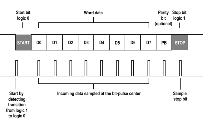
A UART frame
Word length, parity availability and type, and the number of stop bits all have to be agreed in advance.
Because UART uses two wires — one, connecting device A’s transmitter to device B’s receiver, and the other, device B’s transmitter to device A’s receiver — the two participants can send each other data simultaneously, a mode of communications called ‘full duplex’.
imp UARTs
Every imp has on-board support for the UART protocol, with the number of available UART buses ranging from three to four, depending on the type of imp. Each imp’s pin mux table lists all of the choices. This document assumes you are using an imp001 for development, so you should consult the pin mux table if you are working with a different imp. The imp001’s pins offer three possible UART configurations centring on pins 1 and 2; 5 and 7; and 8 and 9. You can select which pair you use.
The pairings 1 and 2; and 5 and 7 are respectively instanced as objects uart12 and uart57 when the imp001 starts up. These objects are made available as properties of the hardware object. In each of these two UART configurations, one pin of the pair is used for transmission — 1 and 5 — and the other for reception — 2 and 7.
The imp001’s third UART option, accessed using the uart1289 object, is slightly different. It uses pins 8 and 9 for, respectively, transmission and reception. Pins 1 and 2 are used to send and receive signals that control the flow of data, specifically CTS (Clear to Send) and RTS (Request to Send) signals. These are optional, and uart1289 can be configured to work without them, just as uart12 and uart57 do.
Configuring UART
The imp API provides all of its UART objects with all the functions you need to establish a conversation with a connected device and to exchange data with it. It’s a good idea to use a global variable as an alias for the particular UART bus you want to use:
uart <- hardware.uart57;
To configure the bus, you need to supply a data rate in bits per second; a ‘word’ size representing the number of data bits you’ll be sending; a constant to indicate what type of ‘parity’ you’ll be using for error correction, if you use one at all; how many stop bits you need to mark the end of your data; and finally a constant which indicates what kind of flow control you want to use. A typical imp UART configuration statement will look something like this:
uart.configure(115200, 8, PARITY_NONE, 1, NO_CTSRTS);
Here the configure() method sets the bus to run at 115,200 bits per second (115Kbps), with eight bits per word, no parity, one stop bit, and no Clear to Send/Request to Send flow control. These parameters define the UART’s frame — the fundamental structure of the data being transmitted.
Let’s look at all of these options. First, speed. Data transfer rates are measured in bits per second. Another unit you may see on datasheets and in the imp API reference is ‘Baud’ — pronounced ‘bowed’ — but it is interchangeable with bits per second: 1bps equals 1 Baud. The range of available baud rates depend on which UART is in use on what imp:
| imp | UART | Minimum baud rate | Maximum baud rate |
|---|---|---|---|
| impC001 | uartDCAB, uartEVMT, uartNU, uartHJKL, uartPQSR, uartXBADC, uartYABCD |
1526 | 12,500,000 (12.5Mbaud) |
| imp003 | All UARTs | 550 | 4,500,000 (4.5Mbaud) |
| imp004m | uartBCAW uartFGJH uartHJ uartQ |
366 732 732 366 |
3,000,000 (3Mbaud) 6,000,000 (6Mbaud) 6,000,000 (6Mbaud) 3,000,000 (3Mbaud) |
| imp005 | uart1 uart0, uart2 |
35 9160 |
2,337,500 (2.34Mbaud) 4,000,000 (4Mbaud) |
| imp001/002 | uart1289 or uart6E All other UARTs |
916 |
7,500,000 (7.5Mbaud) 3,750,000 (3.75Mbaud) |
Not all baud rates can be achieved precisely; the initial configure() call will round the requested rate to the nearest available value, and return the actual baud rate selected as an integer. All the common rates are either exact or very close to exact. Hardware constraints might limit the usability of really fast rates.
You will almost always use eight bits for the word size, but again this will depend on the device you plan to hook up to your imp: check its datasheet. UART can use between five and eight bits per word, but five and six are these days very uncommon, so the imp supports only seven or eight bits per word.
If you are using a 7-bit word, you must to select either PARITY_EVEN or PARITY_ODD as your parity setting. The other option is PARITY_NONE, which is only available if you have selected an 8-bit word length.
Communications that include an even or odd parity bit set that bit’s value to either 0 or 1, according to the results of a calculation applied to all of the bits in the transmitted word. It provides a very basic error checking mechanism: if the data bits come through incorrectly, when the receiver calculates what parity bit value, it may not match the one sent, so the receiver can reject the data as corrupt. Of course, there are instances where calculating the parity of corrupt data will nonetheless produce the correct parity value, but statistically the technique is more likely to be right than wrong. That said, most modern applications of UART are within systems with relatively little data-damaging noise, so you will most likely use PARITY_NONE.
You can select either one or two stop bits, which are used to mark the end of the data frame; a single start bit is always sent before the bits that comprise the data word.
Finally, the flow-control constant is selected from one of the following:
- NO_TX
- NO_RX
- NO_CTSRTS
- CALLBACK_WITH_FLAGS
- TIMING_ENABLED
Only uart1289 (imp001/imp002) has control signals (CTS and RTS); all other UARTs behave as if NO_CTSRTS is always set. On the imp002, uartB has no TX signal, and behaves as if NO_TX is always set. On the imp003, uartQRPW and uartUVGD provide CTS and RTS pins; uartDM, uartFG and uartWJ do not. On the imp004m, uartQ is TX only (NO_RX is implicit) and uartHJ behaves as if NO_CTSRTS is always set; uartBCAW and uartFGJH provide CTS and RTS. On the imp005, uart0 provides CTS and RTS pins; all other UARTs do not. On the impC001, uartDCAB, uartEVMT, uartHJKL, uartPQSR, uartXBADC and uartYABCD provide CTS and RTS pins; all other UARTs do not.
There is one further parameter you may include in the configure() method. It isn’t included in the example above because it is optional and not a part of UART configuration per se. The final parameter the method takes is the name of a function the imp can call if and when it receives a frame. This is a good example of impOS’ event-driven nature: the function is only called when a certain event, in this case the arrival of a byte over a UART link, takes place.
Exchanging Data
Sending information to the connected device is straightforward:
uart.write(someData);
The variable used in the example can be an integer value, a string of characters or a blob. You’ll recall that UART organizes data into frames, and each frame is sent a bit at a time. The imp sorts all this out for you: if you write() a string, the imp will break it down into characters, incorporate each one into a frame and send them off, character by character. It reserves a block of memory as a buffer to hold the frames before they are sent, transmitting them on a first in, first out (FIFO) basis. Advanced users can set the size of the send buffer using the imp API method settxfifosize().
Receiving data works the same way:
local receivedData = uart.read();
Again, incoming frames are dropped into a memory buffer and decoded one by one in the order in which they were received. Advanced users can set the size of the send buffer using the imp API method setrxfifosize(). The method read() returns a single byte of data at a time which you can assign to a variable, in this case receivedData, for processing later. To load more data at a time, when you know how much data is being sent, you can call readstring() or readblob().
The imp API has a number of further UART functions you may need. The first, flush(), causes the output memory buffer to clear itself of pending frames before it will accept any more. This is useful if you need precise control over the sending of individual frames.
The second is disable(). As its name suggests, this method used to temporarily shut down the UART, for either of two reasons. First, you want to save power. UART links, even though they are not transmitting data, are kept at 5V. This is for historical reasons: UART emerged out of wire telegraphy and the voltage had to be maintained so that users could tell if the wire was broken. The disable() method drops the line to 0V. This not only saves the imp power, but it also tells the connected device that the connection has been broken.
To bring the connection back up, run the configure method again. Alternatively — and this is the second reason for using the disable() method — you can now use the Imp pins that have been sending and receiving UART frames for some other task. Until UART is disabled, they can’t be re-used.
A call to flags() returns event flags set by the previous UART transaction. Each flag represents a single bit in the returned value and is cleared after being read. Here are the possible flags:
| Event Flag Constant | Value | Notes |
|---|---|---|
| READ_READY | 1 | Data is available to be read. As per the default callback |
| WRITE_DONE | 2 | Transmit completed |
| NOISE_ERROR | 4 | Noise was detected in the start bit |
| FRAME_ERROR | 8 | The start and stop bits could not be found |
| PARITY_ERROR | 16 | The parity disagrees with that specified by the parity bit |
| OVERRUN_ERROR | 32 | The receive buffer was full when another character arrived |
| LINE_IDLE | 64 | Triggered by an entire frame of 1s followed by the start bit of the next frame which contains data |
Finally, settxactive() configures an imp GPIO pin to be used as a UART-transmit-active indicator. You choose (via the method’s parameters) whether the pin goes high or low when a transmission is taking place. For advanced users, this facility can be used to drive an external RS485 transceiver, for shared-medium (half-duplex) RS485 communications, but it can also drive a UART activity LED, for example.
Example Code
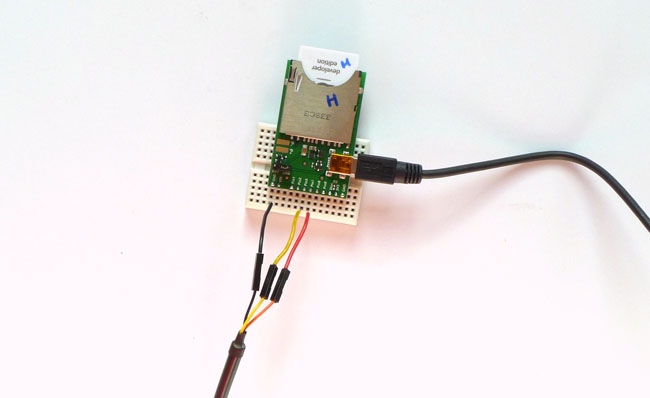
To see how UART works, and how UART communications are established by an imp, try this device code. You will also need a computer with terminal software to connect to, and a USB-to-serial adaptor to carry the data.
Linux and macOS both come with Terminal utilities which can be used run a command-line tool called screen that lets you send and receive serial communications. Windows users should download Simon Tatham’s PuTTY, which combines the role of Terminal and screen.

A USB-to-serial adaptor useful for testing UART links
Many component suppliers offer USB-to-serial cables such as this one. It uses a chip from FTDI to convert UART frames into their USB equivalents. For Windows and Linux, you’ll need drivers and these can be downloaded from the FTDI website; these drivers are built into macOS.
Before you can sent data, you need to locate the representation the computer’s host OS uses to talk to the FTDI chip. On macOS, run Terminal, use the cd command to switch to /dev, the devices directory, and then run ls *cu* to get a list of devices, one of which will be the UART cable. Ignore the Bluetooth entries:
cu.Bluetooth-Modem cu.Bluetooth-PDA-Sync cu.usbserial-FTWHFLU9
Run macOS’ Terminal app, and key in the following to begin reading the UART data stream:
screen /dev/cu.usbserial-FTWHFLU9 115200
Linux also records the cable as a file in its /dev directory, typically as ttyUSB0 or ttyACM0. You will also need to make sure you can access the port’s file by adding your user account to either of the system’s dialout or tty groups, depending which of these the ttyUSB0 is itself a member, which you can do as follows:
ls -la /dev/ttyUSB0
This will show the file’s group, which you can join by entering:
sudo usermod -a -G dialout <your_username>
If the file's group is tty, replace dialout in the above line with tty. Finally, as per macOS, run screen:
screen /dev/ttyUSB0 115200
Windows users should look in Device Manager’s list of ports to find the UART cable after it has been plugged in; you'll need to note down the cable’s COM port number and enter it into PuTTY’s Configuration window, which appears when the program is run. Click on the Serial entry in the PuTTY's Category list on the left side of the window. Here you set the UART speed, data bits, stop bits, parity and flow control information. Make sure XON/XOFF is selected.
Here is the code:
The code aliases one of the imp’s UARTs, which is configured at the end of the listing to match the default values for the screen and PuTTY utilities.
Wiring up the Imp for UART
Writing data to the connected computer takes place in the function loop(). This sends out a string derived from a reading taken from the imp’s on-board light-level sensor. This string is then written out to UART, adding escape codes for a carriage return and a new line so that the output appears in separate lines in the terminal.
The function ends with imp.wakeup() which tells the imp to call loop() again in one second’s time.
The code also reads keypresses entered on the connected computer. The imp’s UART is configured to call a function, readback(), when a byte of data arrives from the remote machine. This byte contains the Ascii code of the key the computer’s user has pressed; the called function calls another which converts the Ascii value into a string character and adds it to a buffer variable called inputString.
When the computer user hits Return, the Ascii code for carriage return, 13, is sent to the imp. The device detects this and displays the buffered characters in impCentral log. It then clears the buffer for any further characters that the computer user keys in.