Using The Grove Connector System
Easily Add Peripherals To The imp006 Breakout Board And Other Developer Kits
The Electric Imp imp006 Breakout Board features two connectors compatible with a peripheral interface called the Grove system. The Grove specification defines a connector and a four-wire interface for hooking up peripheral devices, called ‘modules’, to a host microcontroller. Devised by Seeed, Grove is supported by a wide array of modules, and many of these you can connect to your impC001 or imp006 Breakout Board, or impExplorer, as you evaluate the Electric Imp Platform or work on your connected product prototype.
This guide will help you do so. It introduces the Grove specification with specific reference to its use with the imp006 Breakout Board and other developer kits. It will help you understand what types of modules you can connect to these devices and how, and how you communicate with them through your Squirrel code.
Grove Modules
There are a wide variety of Grove modules available:
The Grove Interface
The Grove connector has four pins numbered one through four, as shown in the image below. The cables are color-coded: red is power and black is ground; this is always the case no matter what peripheral you connect, but pins 1 (yellow) and 2 (white) vary in function according to the Grove module being connected.
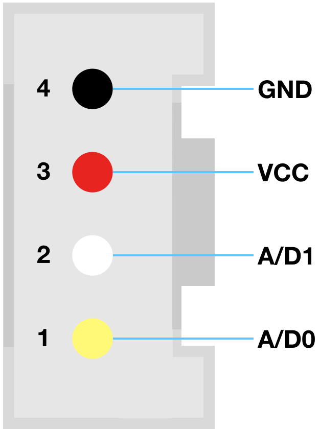
The connector and the port into which it fits are shaped to ensure there is only one way to connect them together.
The Grove system supports four modes:
Digital
In digital mode, pins 1 and 2 are considered, respectively, primary and secondary digital input/output. Most digital Grove modules only use pin 1. However, a few modules, such as Seeed’s LED bar display, use both pins 1 and 2. The impC001 Breakout Board and the imp004m-based impExplorer are compatible with all modules, but the imp001-based impExplorer is compatible only with modules which use pin 1 only.
On the imp006 Breakout Board, the digital connector is marked Grove, and is connected as follows:
| Grove Connector | Digital 1 (Yellow) | Digital 2 (White) | Mode |
|---|---|---|---|
| D/A | hardware.pinN | hardware.pinXN | Input and Output |
On the impC001 Breakout Board, the digital connector is marked Grove, and is connected as follows:
| Grove Connector | Digital 1 (Yellow) | Digital 2 (White) | Mode |
|---|---|---|---|
| D/A | hardware.pinYP | hardware.pinYQ | Input and Output |
On the imp004m impExplorer, the digital connectors are marked Grove Analog/Digital and are connected as follows:
| Grove Connector | Digital 1 (Yellow) | Digital 2 (White) | Mode |
|---|---|---|---|
| D0 | hardware.pinC | hardware.pinB | Input and Output |
| D1 | hardware.pinD | hardware.pinK | Input and Output |
If you are not using the imp004m impExplorer’s I²C connectors or the internal sensors, these can be used as digital IO by configuring pins Q and P:
hardware.pinQ.configure(DIGITAL_OUT, 1);
hardware.pinP.configure(DIGITAL_OUT, 1);
On the imp001 impExplorer, the digital connectors are also marked Grove Analog/Digital and are connected as follows:
| Grove Connector | Digital 1 (Yellow) | Digital 2 (White) | Mode |
|---|---|---|---|
| D0 | hardware.pin2 | Not connected | Input and Output |
| D1 | hardware.pin5 | Not connected | Input and Output |
However, if you are not making use of the imp001 impExplorer’s I²C connectors or the internal sensors, these can be used as digital IO by configuring pins 8 and 9:
hardware.pin8.configure(DIGITAL_OUT, 1);
hardware.pin9.configure(DIGITAL_OUT, 1);
For example, the Seeed 4-Digit Display uses pins 1 and 2 as, respectively, clock and data signalling pins. These can be accessed on the imp001 impExplorer with pin 8 and pin 9. This is supported by Electric Imp’s Grove TM1637 library, which provides an easy way to drive the display from your device code.
Note Both connectors are wired in parallel to pins 8 (yellow) and 9 (white). The Seeed Grove switch uses the yellow pin only, so you can connect such a switch to either of the connectors and read its state using pin 8. You can’t connect another of these switches and expect to read its state using pin 9: you will need a different switch, one that uses the white wire.
Analog
Analog operation is an alternative mode to digital. Again most Grove modules only make use of pin 1, but some may use pin 2 too.
The imp006 Breakout Board’s Grove connector supports analog input only:
| Grove Connector | Digital 1 (Yellow) | Digital 2 (White) | Mode |
|---|---|---|---|
| D/A | hardware.pinN | hardware.pinXN | Input Only |
The impC001 Breakout Board’s Grove connector supports analog input only:
| Grove Connector | Analog 1 (Yellow) | Analog 2 (White) | Mode |
|---|---|---|---|
| D/A | hardware.pinYP | hardware.pinYQ | Input Only |
On the imp004m impExplorer, the analog pins support analog input only:
| Grove Connector | Analog 1 (Yellow) | Analog 2 (White) | Mode |
|---|---|---|---|
| A0 | hardware.pinC | hardware.pinB | Input Only |
| A1 | hardware.pinD | hardware.pinK | Input Only |
On the imp001 impExplorer, pin 2 can only be used for analog input, but pin 5 supports both input and output:
| Grove Connector | Analog 1 (Yellow) | Analog 2 (White) | Mode |
|---|---|---|---|
| A0 | hardware.pin2 | Not connected | Input Only |
| A1 | hardware.pin5 | Not connected | Input and Output |
Again, the imp001 impExplorer’s I²C head may be co-opted as analog inputs by configuring pins 8 and 9:
hardware.pin8.configure(ANALOG_IN);
hardware.pin9.configure(ANALOG_IN);
I²C
There are many types of I²C Grove sensors available, and while most support 3.3V signalling, some are 5.0V-only, so check before buying. These devices will need intermediate level reduction to be used with either impExplorer or the impC001 Breakout Board, all of which only support 3.3V signalling.
All Grove I²C connectors use pin 1 (yellow wire) as SCL (clock) and pin 2 (white wire) as SDA (data). The impC001 Breakout Board has only one I²C connector. It is wired up to the impC001’s hardware.i2cXDC bus. The imp006’s single I²C connector is wired to hardware.i2cTU.
The imp004m impExplorer’s two I²C headers are both connected to the imp004m’s pins Q (SCL) and P (SDA). Tying two headers to a single pair of pins is not an issue because I²C supports multiple devices on the same lines: each device is signalled at a different address. Note that the imp004m impExplorer’s on-board sensors also connect via I²C through hardware.i2cQP.
The imp004m impExplorer’s two I²C headers are both connected to the imp001’s pins 8 (SCL) and 9 (SDA). The imp001 impExplorer’s on-board sensors also connect via I²C through hardware.i2c89.
UART
The Grove specification provides for UART signalling, but this is not supported by the the imp001 impExplorer, the impC001 Breakout Board or the imp006 Breakout Board. However, the imp004m’s inner digital/analog connector supports UART RX and TX on pins C and D, respectively, which are accessed via hardware.uartBCAW (configured with NO_CTSRTS).
Powering Grove Connectors
imp006 Breakout Board
Power to both of the imp006 Breakout Board’s Grove headers is gated by pin XU, which must be set HIGH to power Grove peripherals. Alternatively, solder bridge W2 on the board to force Grove power on.
impC001 Breakout Board
Power to both of the impC001 Breakout Board’s Grove headers is gated by pin YG, which must be set HIGH to power Grove peripherals.
Working with Grove Modules in Squirrel
Simple digital and analog modules are relatively easy to work with. Whichever Analog/Digital header that you connect the module to, you access it through that header’s pin 1 (imp001 impExplorer) or pins 1 and 2 (imp006 Breakout Board, impC001 Breakout Board and imp004m impExplorer).
Depending on the module, you just use Squirrel to configure the pin to meet your needs. For example, to read an analog signal coming in on the imp006 Breakout Board, you would use the following Squirrel code, which will run on any of the boards discussed here:
// Alias the imp pin according to the board we're using
local analogPin = null;
local type = imp.info().type;
if (type == "imp006") {
    // imp006 Breakout Board
    analogPin = hardware.pinN;
} else if (type == "impC001") {
    // impC001 Breakout Board
    analogPin = hardware.pinYP;
} else if (type == "imp004m") {
    // imp004m impExplorer
    analogPin = hardware.pinC;
} else {
    // imp001 impExplorer
    analogPin = hardware.pin2;
}

// Configure the pin
analogPin.configure(ANALOG_IN);

function readLoop() {
    local reading = analogPin.read();
    server.log("Analog pin reading: " + reading);
    imp.wakeup(1.0, readLoop);
}

// Start the reading cycle
readLoop();
More complicated devices, in particular I²C modules, will require slightly more complex Squirrel. Setting up I²C communications is straightforward, but you will need to examine the specific module’s datasheet to understand what commands you need to issue to initialize it and make use of it. Our article I²C Explained, will help you if you haven’t worked with I²C before.
Fortunately, there is a growing selection of Electric Imp code libraries which support the sensors and other devices that form the basis for many Grove modules. These libraries can be easily added to your application code and provide simple APIs for accessing module features. In short, they do all the I²C heavy lifting for you, so you can focus on your application.
For example, the TSL2561 library supports the I²C-connected TSL2561 digital ambient light sensor. Just paste the library code into your device code, then and instantiate and configure it as follows:
local sensor = null;
local type = imp.info().type;
if (type == "imp006") {
    // imp006 Breakout Board
    hardware.i2cTU.configure(CLOCK_SPEED_400_KHZ);
    sensor = TSL2561(hardware.i2cXDC);
} else if (type == "impC001") {
    // impC001 Breakout Board
    hardware.i2cXDC.configure(CLOCK_SPEED_400_KHZ);
    sensor = TSL2561(hardware.i2cXDC);
} else if (type == "imp004m") {
    // imp004m impExplorer
    hardware.i2cQP.configure(CLOCK_SPEED_400_KHZ);
    sensor = TSL2561(hardware.i2cQP);
} else {
    // imp001 impExplorer
    hardware.i2c89.configure(CLOCK_SPEED_400_KHZ);
    sensor = TSL2561(hardware.i2c89);
}
You can then get a reading as follows:
sensor.read(function(result) {
    // Callback function triggered when a reading is available
    if (result == null) {
        server.error("An Error Occurred");
    } else {
        server.log(format("Ambient light value: ", result));
    }
});
For modules not yet supported with an Electric Imp library, there are generally simple drivers written by Seeed which support the module on the Arduino platform. These drives are usually very straightforward to convert to Squirrel, for which our guide Porting Arduino Code To The imp provides full details.