imp003 Breakout
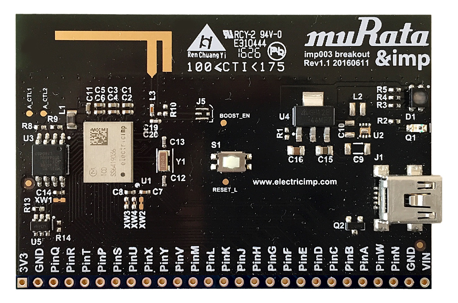
The imp003 breakout board provides a standard platform for imp003 (Murata LBWA1ZV1CD) product development. The design includes power supply and GPIO breakout for the module, as well as a WiFi antenna, 32kHz crystal (for maintaining the real-time clock when offline), load switch for the radio power domain, and the required SPI Flash.
Note Images may not represent the current version of the design.
Purchase
This product is available to purchase from Mouser and Digikey.
Setup
To set up an imp003 Breakout Board, please see this page.
GPIO Pinout Chart
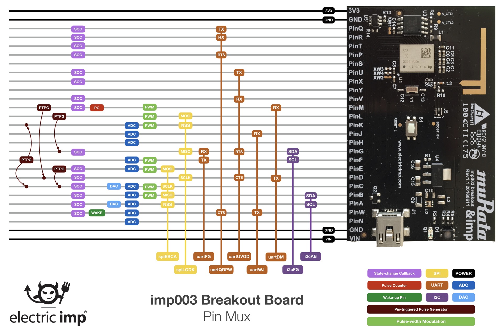
Click for larger version
Power
Power can be supplied using a USB Mini-B cable from a USB Charger or a standard USB Port, though the data lines are disconnected. Optionally, power can be provided through the VIN header on the board edge.
The imp003 breakout board includes footprint options for two different power supplies. By default, a 3.3V LDO is populated as the system power supply. Using the LDO power supply, it is not recommended that the supply voltage exceed 6V, for heat dissipation reasons.
Alternatively, footprints are included for a TI TPS62172 DC/DC buck power supply. If this option is used in place of the LDO, the board can safely be operated from 3.3V to 17V DC.
Both power supply options include reverse-voltage protection, which is especially helpful for any application with removable batteries where they may be inserted backwards by the user.
The USB connector should not be connected if power is provided through the VIN header on the board edge.
Signals
All of the signals from the imp003 come out to a header. For descriptions of header pin functions, please see the imp003 pin mux.