imp005-EZ Eval Kit
The Electric Imp imp005-EZ Eval Kit provides an easy way for customers to evaluate the functionality of the imp005 module and the imp005-EZ card. Packaged in an Arduino®-style form-factor, this kit features both wireless connectivity (using the on-board dual-band 802.11n WiFi) and wired connectivity via a 10/100Mb/s Ethernet jack.
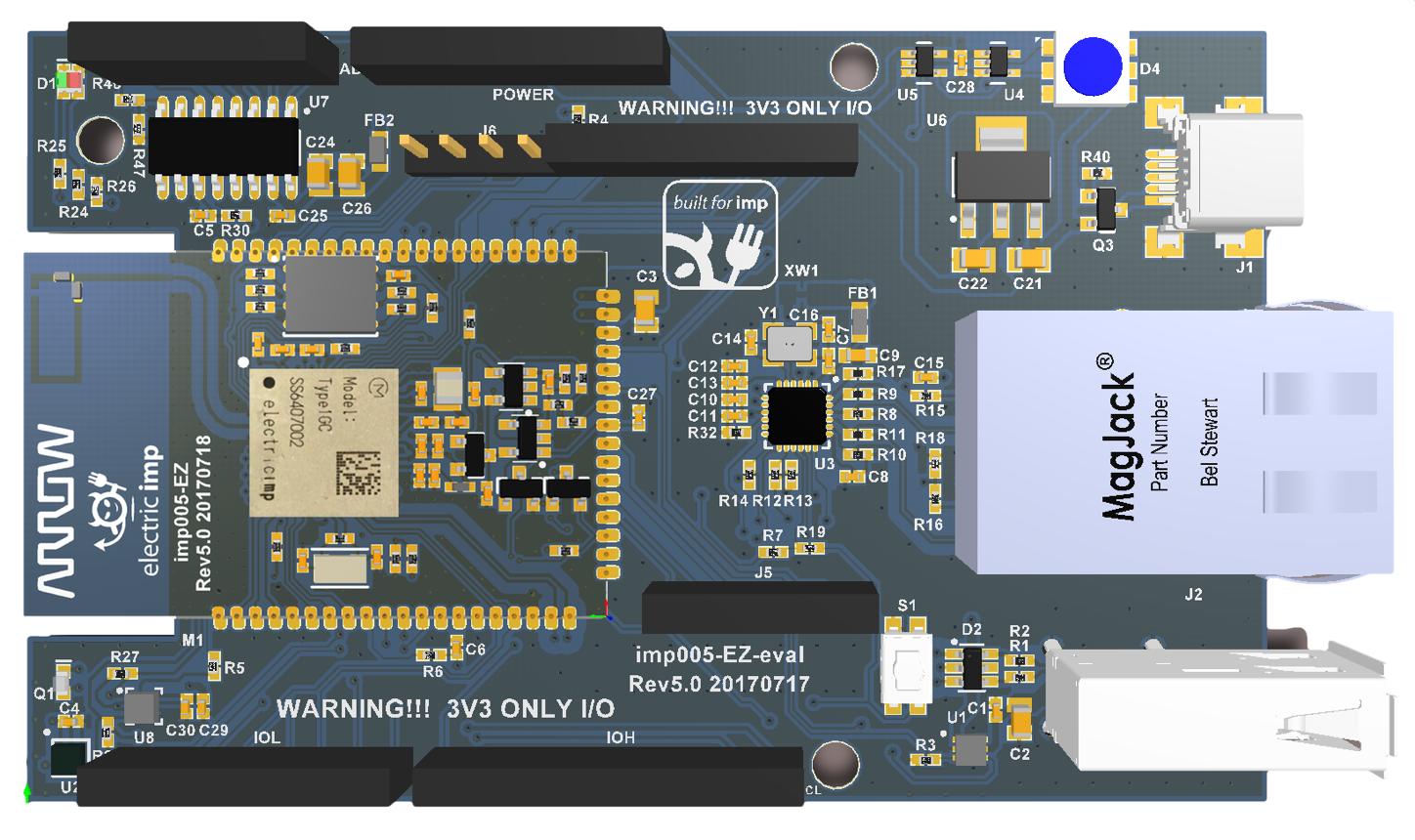
In addition to compatibility with 3.3V Arduino shields, the imp005-EZ Eval Kit has a USB 2.0/1.1 Low-Speed/Full-Speed host port, temperature/humidity sensor, MCP3208 ADC and APA102 RGB LED to enable simple applications to be run right out of the box.
For full set-up instructions and sample code, please see our imp005-EZ Eval Kit Getting Started Guide.
Key Features
Connectivity
- Dual-band (2.4GHz and 5GHz) 802.11abgn WiFi via integrated antenna
- WAN Ethernet via RJ45 connector
- USB 2.0/1.1 Low-Speed/Full-Speed host
Electric Imp Module
Environment Sensors
- HTS221 Temperature and humidity
- LIS2DH12 Motion in three axes
Expansion
- Arduino Shield-compatible headers
Analog Voltage Measurement
- MCP3208 ADC connected via SPI.
Application Feedback
- APA102 RGB LED
Hardware Details
Sensors
The imp005-EZ Eval Kit incorporates two components for environment sensing:
| Sensor | Measured Quantity | I²C Address (8-bit) | Datasheet | Library (click link for latest version) |
|---|---|---|---|---|
| HTS221 | Temperature and humidity | 0xBE | Link | HTS221.device.lib.nut |
| LIS2DH12 | Motion in three axes | 0x32 | Link | LIS3DH.class.nut |
The LIS3DH library supports the LIS2DH12.
ADC
The MCP3208 ADC is connected via the imp005 module’s SPI 0 bus (accessed in application code using hardware.spi0). It can be used to measure the analog pins on the Arduino header and a divided down version of the board VIN.
USB Host Port
The imp005-EZ Eval Kit can operate as a USB host for USB 1.1/2.0 devices using the USB A connector on the PCB. Only one USB device may be connected at any one time, and USB hubs are not supported. Please see the impOS USB API for further details on the classes used to manage the imp005-EZ Eval Kit’s USB connection.
The USB port supplies a current-limited 5V for USB devices with maximum recommended load of 500mA. USB power is controlled by the imp005’s GPIO pin R and overcurrent on USB events are reported via GPIO pin W. For more information, please see the imp005 Hardware Design Guide.
| imp005 Pin | Function |
|---|---|
| R | USB power enable |
| W | USB overcurrent indication |
| USB2_DP | D+ |
| USB2_DN | D- |
Please see the imp API usb object for more information on programming the imp005-EZ Eval Kit to interact with USB devices.
WAN Ethernet Port
The Wide Area Network (WAN) Ethernet port allows the imp005 to connect to the Electric Imp impCloud™ via a wired connection for applications where WiFi is not available or the stability of a wired connection is preferred.
APA102 RGB LED
The APA102 RGB LED is connected to the imp005-EZ Eval Kit’s power and GND lines. To control the LED, use pin T (clock) and Y (data). The APA102 datasheet shows how to transmit data: essentially, write the data bit value to data then send a pulse out via the clock pin. The APA102 reads its data input whenever it detects a rising edge on its clock line.
LED data is structured as follows: four bytes each of 0x00 (start frame), four bytes of data per LED and then four bytes each of 0xFF (end frame). The LED data frame comprises a ‘Global’ byte (Bits 7 through 5 are all 1; the remainder set the LED brightness) plus three bytes each for the LED’s blue, green and red color component values.