imp004m impExplorer Kit
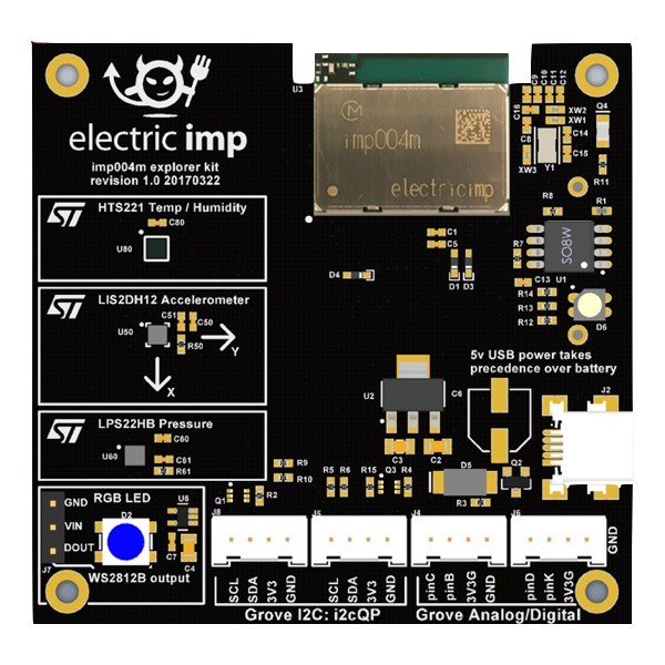
The Electric Imp imp004m impExplorer™ Kit is the ideal basis for building self-contained connected devices. It includes not only a trio of temperature and humidity, motion, and pressure sensors, but also an RGB LED for visible feedback. In addition, it provides Grove System headers for expansion. Two of these connectors are intended for I²C peripherals, the others for analog and/or digital devices.
Pinout Chart
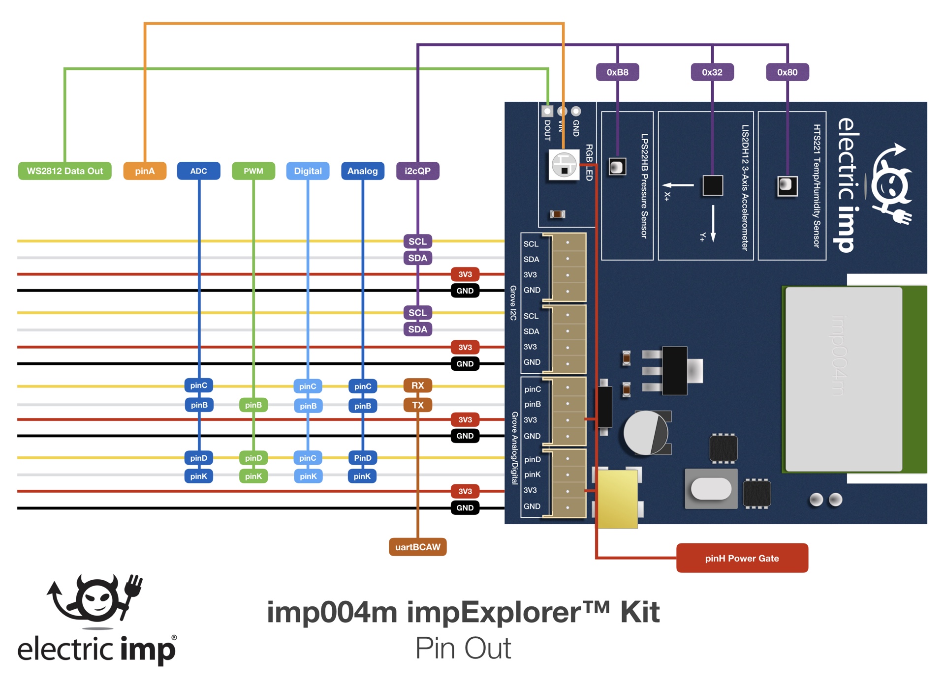
Click for larger version
Power
The imp004m impExplorer Kit can be powered either by a standard mini USB cable fed from an AC adaptor or a suitable (ie. powered) USB port on another device, such as a computer, TV or set-top box. The Kit’s USB port is wired for power only — no data can be exchanged this way.
The underside of the imp004m impExplorer Kit is fitted with a holder for three AA batteries. If you choose to fit rechargeable cells, please be aware that the imp004m impExplorer Kit does not include charge management circuitry — your cells will need to be recharged externally.
The imp004m impExplorer Kit will always use USB power, if present, in preference to battery power.
Power Gate
The imp004m impExplorer Kit is power gated, with control of the gate applied to hardware.pinH. To support high-power (5V) peripherals, such as the the RGB LED, and to make use of the Grove Analog/Digital ports, make sure you include the following line at the start of your device code:
hardware.pinH.configure(DIGITAL_OUT, 1);
imp004m impExplorer Kit Sensors
The imp004m impExplorer Kit incorporates three components for environment sensing:
| Sensor | Measured Quantity | I²C Address (8-bit) | Library | Datasheet |
|---|---|---|---|---|
| HTS221 | Temperature and humidity | 0xBE | HTS221.device.lib.nut | Link |
| LIS2DH12 | Motion in three axes | 0x32* | LIS3DH.class.nut | Link |
| LPS22HB | Air pressure | 0xB8 | LPS22HB.class.nut | Link |
* This is not the sensor’s default I²C address, so you will need to add its address into the class constructor of its Electric Imp library.
All of the sensors can be easily accessed in application code using the Electric Imp libraries named in the table above. Click the library links for the latest version. Note The LIS2DH12 intentionally makes use of the LIS3DH library as these two devices are functionally equivalent.
All three sensors operate over I²C and connect to the on-board imp004m’s hardware.i2cNM bus. In addition, each sensor has an interrupt line used for signalling critical value alerts. All of these lines connect to the imp004m’s hardware.pinW: an interrupt from any of the sensors will cause hardware.pinW to be high.
RGB LED
The imp004m impExplorer Kit’s RGB LED is a WS2812B device which can be accessed via the imp004m’s hardware.spiAHSR bus set to MSB_FIRST mode and a speed of 7500KB/s. Only imp004m pin A is actually used in this role.
The LED is best driven in application code via Electric Imp’s WS2812 library (click the link for the latest version):
to the top of your device code. You will also need to add the following line at the start of your device code:
hardware.pinH.configure(DIGITAL_OUT, 1);
Grove System Headers
The imp004m impExplorer Kit incorporates four Grove System-compatible headers, each of which connects to a four-wire cable with two data wires (yellow and white) plus 3V3 (red) and GND (black). For more information on the Grove System, please see the Seeed Wiki.
- See also Using the Grove Connector System
I²C
The data wires can be used to drive a variety of Grove-compatible devices, though only those which operate over I²C are supported by the impExplorer Kit’s two Grove I²C headers, both of which connect to the imp004m’s hardware.i2cQP bus. The yellow wire provides the clock line; the white wire the data line. Only 3V3 I²C devices are supported.
Analog and Digital
The other two headers are intended for Grove Analog and/or Grove Digital peripherals — the two headers are connected to the imp004m’s hardware.pinC (yellow), hardware.pinB (white), hardware.pinD (yellow) and hardware.pinK (white).
For Analog/Digital operation, you will need to add the following line at the start of your device code:
hardware.pinH.configure(DIGITAL_OUT, 1);