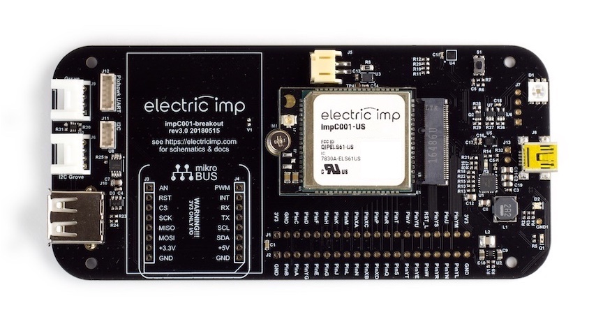
impC001 Breakout Board
The impC001 Breakout Board provides a full product evaluation, code development and product prototyping platform for the cellular impC001. It includes not only comprehensive power management circuitry and a set of temperature, humidity and motion sensors, but also an RGB LED for visual feedback. Almost all of the impC001’s GPIO pins and standard buses are exposed on 0.1" headers.
In addition, the impC001 Breakout Board includes a pair of Grove System headers for expansion. One of these headers is intended for I²C peripherals, the other for analog and/or digital devices. Further expansion is provided by a header for a mikroBUS™ connector which, when populated with connectors, can take a wide range of MikroElectronica Click™ devices. It can be fitted into a New Age Enclosures case.
Finally, the impC001 Breakout Board includes a USB Type A host port to which a single device may be connected and accessed via application code.
Note Images may not represent the current version of the design.
Device Activation
Please see Getting Started With The impC001 Breakout Board for detailed guidance on connecting a new board to the Electric Imp impCloud™ and adding it to your Electric Imp account.
Hardware Features
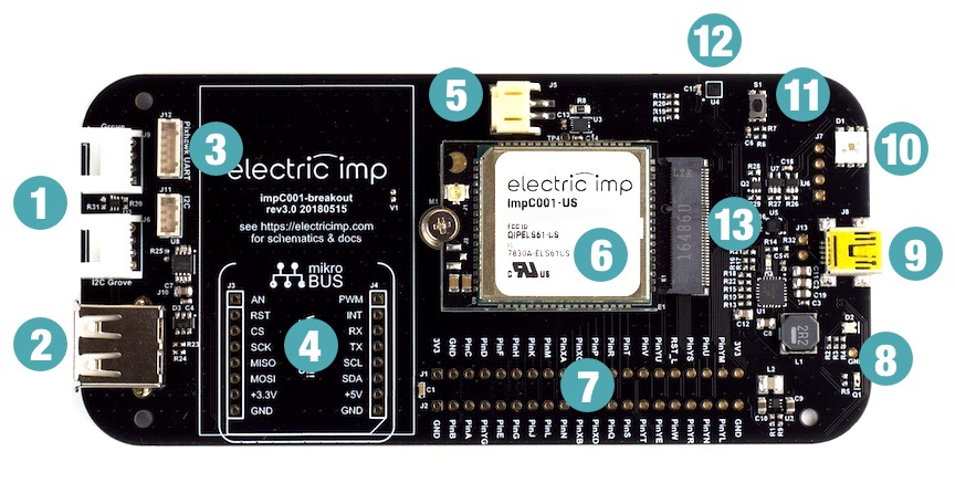
- Grove connectors (digital/analog and I²C)
- USB A host
- Pixhawk GPS/compass connectors
- mikroBUS Click slot header
- Li-Ion battery connector
- impC001 module
- GPIO header pins
- BlinkUp™ sensor and status LED
- Mini USB (power only)
- User RGB LED
- Reset switch
- Temperature and humidity sensor
- Motion sensor
Hardware Details
Power
The impC001 Breakout Board includes a mini USB port for power input, and a standard JST Li-Ion/Li-Poly battery connector. The board will run without a battery attached when using the included power adaptor.
Note When the impC001 connects via 2G, we recommended that the breakout board is powered by battery. 2G operation requires higher current supply than LTE operation does, and USB may not be able ot provide sufficient current.
Mini USB
The D+/D- lines on the mini USB connector are attached to the PMU, which automatically performs power source identification and sets the appropriate current limit (0.5A, 1.0A, 2.1A, 2.4A) when used with off-the-shelf phone charger bricks or computer USB host ports. The board is supplied with a 2.1A brick for US/AUS variants, and a 2.4A brick for EU variants due to the current requirements of 2G networks.
Direct 5V Input
You can also power the board by connecting a 5V source to J13 (directly to the left of the USB connector). The square pin (pin 1) is GND.
If you would like the board to not be current limited (because J13 is the only power input), bridge the W1 connectors on the underside of the PCB with solder. This lets the PMU know that the input is not current limited.


Battery
A Maxim Integrated MAXI17055 single-cell gas gauge IC and a Texas Instruments BQ25895 power management unit are included on the board. These components allow the board to manage an attached Li-Ion/Li-Poly battery and monitor its charge level.
Charge/power management is automatic, so with a battery fitted the device will run the load from the input power directly, with any unused power within the input current limit being used to charge the battery. If the load is higher than the input current limit, power will be drawn from both the external input and the battery.
The default configuration for the charger is a 2A charge rate. As such, a 2000mAh or larger 1S Li-Ion/Li-Poly battery should be used unless you are either using a limited power source, or reprogram the charge rate at startup. Libraries for these two components are linked at the bottom of this page, and they are accessed via the impC001’s hardware.i2cKL bus.
A suitable battery can be obtained from Adafruit or one of their resellers.
Sensors
The impC001 Breakout Board includes the following sensors:
| Sensor | Measured Quantity | I²C Address (8-bit) | Library | Datasheet | Example |
|---|---|---|---|---|---|
| HTS221 | Temperature, humidity | 0xBE | HTS221.device.lib.nut | Link | Sample Code |
| LIS2DH12 | Motion in three axes | 0x32* | LIS3DH.class.nut | Link |
*This is not the sensor’s default I²C address, so you will need to add its address into the class constructor of its Electric Imp library.
All of the sensors can be easily accessed in application code using the Electric Imp libraries named in the table above. Click the library links for the latest version.
Note The LIS2DH12 intentionally makes use of the LIS3DH library as these two devices are functionally equivalent. These sensors are accessed via the impC001’s hardware.i2cKL bus.
Note The board’s built-in sensors will be on the same I²C bus as the mikroBUS connector and Pixhawk magnetometer, if you have one, so please check for I²C address clash if you are using more than one of these peripherals.
RGB LED
The impC001 Breakout Board’s RGB LED is an APA102, an all-in-one RGB LED with integrated shift register and constant-current driver. It can be accessed via the impC001’s hardware.spiYJTHU bus set to SIMPLEX_TX mode and a speed of 7.5MHz. As with other peripherals which would affect sleep power, the LED power is gated by pin YG, which should be driven HIGH before attempting to use the peripheral.
The LED is best driven in application code via Electric Imp’s APA102 library (click the link for the latest version). Add #require "APA102.device.lib.nut:2.0.0" to the top of your device code. For example:
#require "APA102.device.lib.nut:2.0.0"

// Turn on power to peripherals
hardware.pinYG.configure(DIGITAL_OUT, 1);

// Instantiate LED array with 1 pixel
hardware.spiYJTHU.configure(SIMPLEX_TX, 7500);
local pixel = APA102(hardware.spiYJTHU, 1);
local state = true;

function loop() {
    pixel.set(0, (state ? [255,0,255] : [0,0,0])).draw();
    state = !state;
    imp.wakeup(1, loop);
}

// Start the loop
loop();
Grove Connectors
The impC001 Breakout Board incorporates two Grove System-compatible headers, each of which connects to a four-wire cable with two data wires (yellow and white) plus 3V3 (red) and GND (black). For more information on the Grove System, please see the Seeed Wiki. Power to both Grove headers is gated by pin YG, which must be set HIGH to power Grove peripherals.
- See also Using the Grove Connector System
Analog and Digital
One header is intended for Grove Analog and/or Grove Digital peripherals: its A0/D0 (yellow) and A1/D1 (white) lines are connected, respectively, to the impC001’s pins YP and YQ.
I²C/UART
The other header can be used to drive a variety of Grove-compatible devices which operate over I²C or UART. When configured for I²C, devices are accessed using the impC001’s hardware.i2cJH bus. The yellow wire provides the clock line; the white wire the data line. Only 3V3 I²C devices are supported. When configured for UART, devices are accessed using the impC001's hardware.uartHJKL interface, set to NO_CTSRTS. The yellow wire provides the host RX line, and the white wire the TX line.
mikroBUS
The impC001 Breakout Board provides an optional header pins to allow you to install a mikroBUS connector. Such a connector allows you to fit Click boards (not included) from MikroElectronica. Click is an ecosystem of available modules adding support for current loop communication, thermocouples, 1-Wire® devices and many others.
SPI, UART and I²C interfaces are available through the mikroBUS header, and additional Click control signals are connected to the impC001 GPIO and can be controlled via firmware. 3.3V power to the Click board is gated by pin YG, which must be set HIGH to enable the power supply. The supply is gated to allow low power sleeping even with high current Click boards fitted.
Note that though 5V is available on this connector (connected to the USB host connector 5v rail), all the I/Os are 3.3v only. Please ensure that the clicks you fit are 3.3v compatible.
| Click Pin No. | Click Name | Description | impC001 Pin |
|---|---|---|---|
| 1 | AN | Analog | YK |
| 2 | RST | Reset | YC |
| 3 | CS | SPI Chip Select | S |
| 4 | SCLK | SPI Clock | R |
| 5 | MISO | SPI Master In | Q |
| 6 | MOSI | SPI Master Out | P |
| 7 | 3V3 | ||
| 8 | GND | ||
| 9 | GND | ||
| 10 | 5V0 | ||
| 11 | SDA | I2C Data | L |
| 12 | SCL | I2C Clock | K |
| 13 | TX | UART TX (to Click) | YA |
| 14 | RX | UART RX (from Click) | YB |
| 15 | INT | Hardware interrupt | YD |
| 16 | PWM | Pulse Width Modulation signal to Click | YT |
Note The mikroBUS connector will be on the same I²C bus as the board’s built-in sensors and a Pixhawk magnetometer, if you have one, so please check for I²C address clash if you are using more than one of these peripherals.
USB Host Port
The impC001 Breakout Board can operate as a USB host for USB 1.1/2.0 FS/LS devices using the USB Type A connector on the PCB. Only one USB device may be connected at any one time, and USB hubs are currently not supported.
The USB port’s D+ and D- pins are connected to the impC001’s pins A and B, respectively, and the bus can be operated using the impC001’s hardware.usbAB bus. Please see the impOS™ USB API for further details on the classes used to manage the board’s USB port.
The USB port supplies a current-limited 5V for USB devices with maximum recommended load of 500mA. USB power is controlled by the impC001’s GPIO pin YM (active HIGH) and overcurrent on USB events are reported via GPIO pin YN (active LOW, enable a pull-up on this pin to read the state). 5V is supplied to the port from one of three sources, selected by by a jumper at J14.
The default power source is USB INPUT. Selecting this source makes 5V available on the USB host port when the breakout board is powered by the USB input; when the unit is running from a battery, this 5V source is however not available.
Selecting PMU BOOST will power the USB port from the boost output of the battery charge controller. This 5V output is available when the battery is powering the breakout board, but is not available during charging.
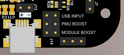
The third power option is to install a boost module as U9. If installed and MODULE BOOST is selected at J14, this will provide 5V to the USB host port at all times, as this boosts the VMOD_GATED rail to 5V. Because VMOD_GATED is controlled by pin YG, this must be set HIGH in addition to the USB power gate control pinYM to enable USB host power.
| impC001 Pin | USB Function |
|---|---|
| A | D+ |
| B | D- |
| YM | Power enable |
| YN | Overcurrent indication |
Pixhawk GPS
The impC001 Breakout Board provides a connector (J12) for the connection of Pixhawk GPS modules. These modules, built to provide GPS functionality to drone autopilot systems, are a very cost-effective way to buy high-end GPS devices such as the Ublox M8N or Ublox LEA-6H. The modules almost always contain a backup power source for the GPS, ensuring that the module will retain its almanac data during power outages and reducing time to first fix.
You can get M8N modules from many retailers, including Amazon.
Pin 1 (top) provides power; pin 6 (bottom) is GND. The data pins are 2 and 3 which are connected to the the impC001’s pins N and U, respectively, so are ready to be used with the imp API object hardware.uartNU configured as NO_CTSRTS. Power to the GPS module is gated by pin YG, which must be set HIGH to power the GPS.
| J12 Pin | Role | impC001 Pin |
|---|---|---|
| 1 | 3V3 | 3V3 |
| 2 | UART RX | N |
| 3 | UART TX | U |
| 4 | ||
| 5 | ||
| 6 | GND | GND |
To help you manage a connected GPS module, Electric Imp provides two libraries: GPSUARTDriver, which handles the hardware interface, and GPSParser, which you can use to decode GPS data issued by the module.
Many Pixhawk modules also contain a magnetometer (compass) connected via I²C. This connection is available on J11, and can be accessed through the impC001’s hardware.i2cKL bus. Power is not provided on this connector.
| J11 Pin | Role | impC001 Pin |
|---|---|---|
| 1 | ||
| 2 | I²C SCL | K |
| 3 | I²C SDA | L |
| 4 | GND | GND |
Note The magnetometer will be on the same I²C bus as the board’s built-in sensors and mikroBUS connector so please check for I²C address clash if you are using more than one of these peripherals.
Known Issue
If you are using a Pixhawk magnetometer on J11, we recommend inserting a half-second pause (imp.sleep(0.5);) between setting the power gate (pin YG) HIGH (in order to power the Pixhawk) and instantiating the board’s sensors. During Pixhawk power up, the GPS unit can introduce electrical instabilities on the I²C bus that affect communication between the imp and the sensors, causing sensor class instantiation failures. The Squirrel pause ensures the sensors have access to settled bus lines.
GPIO Pins
Please see the impC001 Pin Mux page for information on all of the many GPIO pins and standard buses made available by the impC001 module and exposed via the Breakout Board.
Accessories
The impC001 Breakout Board has been designed to fit in the following enclosures: