impAccelerator Battery Powered Sensor Node
The impAccelerator™ Battery Powered Sensor Node is a complete housed environmental sensing package to help you quickly develop and refine data-gathering modules that are able to operate for years at a time from standard AA batteries.
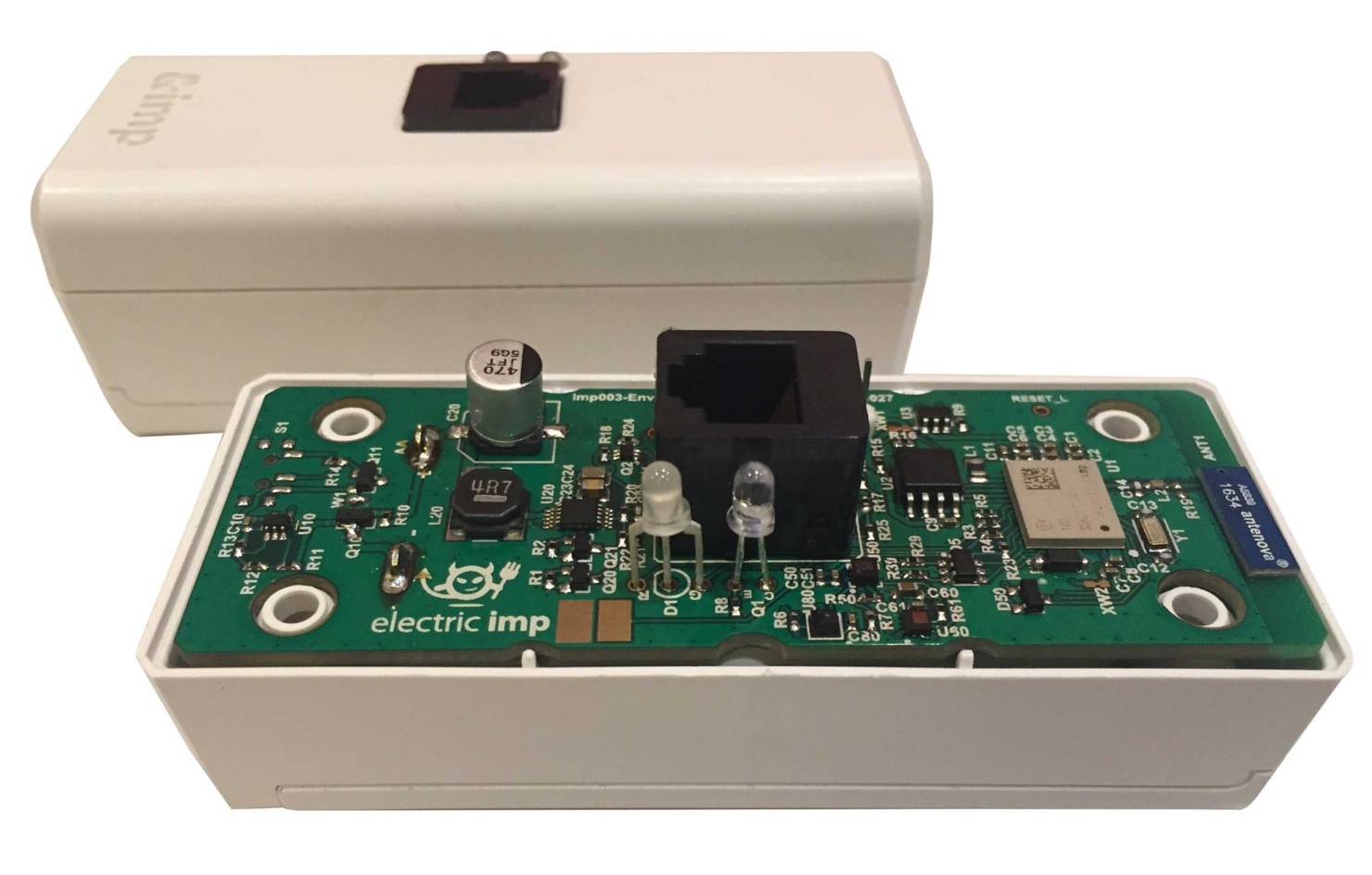
In addition to a raft of on-board sensors for metrics including temperature, humidity, air pressure and motion, the unit also supports the addition of 1-Wire®, UART and I²C interface devices.
Application Examples
Thanks to the Electric Imp Platform’s reliable networking and robust security — delivered through the impCloud™ and impOS™ — and the imp003 module’s ability to run fully customizable application software, the Battery Powered Sensor Node can be used to kick-start the development of a wide range of sensor applications, including:
- Refrigeration or climate control monitoring (using built-in temperature, humidity and light sensors).
- Food and beverage monitoring (using food-grade 1-Wire sensors).
- Asset monitoring (using built-in accelerometer).
- Air quality monitoring (using 1-Wire air and gas sensors).
- Industrial process monitoring (using built-in sensors or additional industrial 1-Wire sensors).
- Local or remote alerting (using external sound/light/actuators).
Open Source Design And Optimized Bill Of Materials
The impAccelerator Battery Powered Sensor Node is an open source design with an optimized Bill of Materials (BoM). This allows customers to seamlessly scale from Proof of Concept to product deployment in volume with cost-optimized hardware designs and reusable software.
For production in 1k volume, the expected BOM for the Battery Powered Sensor Node design is around $24.46 (all features included).
Key Features
Connectivity
- Single-band (2.4GHz) 802.11bgn WiFi with integrated Antenova antenna
Electric Imp Module
- imp003 (Murata Type 1CD)
On-board Sensors
- STMicroelectronics LIS2DH12TR (Three-axis Accelerometer)
- STMicroelectronics LPS22HB (Air Pressure)
- STMicroelectronics HTS221 (Temperature and Humidity)
Expansion
- RJ-12 connector for external 1-Wire, UART and/or I²C devices
- NTC thermistor connection pads
- FTDI serial debugging header
Power Source Options
Internal bay for two standard AA cells (fitted)

External Features
Front Panel
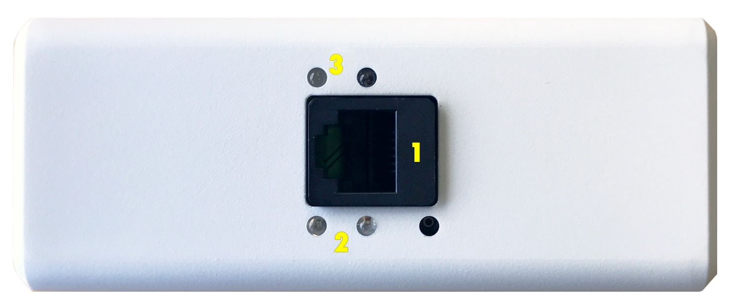
- RJ-12 port for 1-Wire
- BlinkUp sensor and status LED
- User-controllable status LEDs
Internal Features
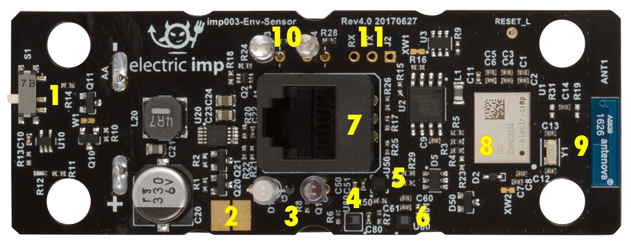
- Battery power switch
- NTC thermistor pads
- BlinkUp status LED and sensor
- HTS221 sensor
- LIS2DH12TR sensor
- LPS22HB sensor
- RJ-12 port
- imp003 module
- Antenova high-performance WiFi antenna
- User-controllable status LEDs
- FTDI header (RX, TX, J2)
Set Up
To set up a Battery Powered Sensor Node, please see this page.
Hardware Details
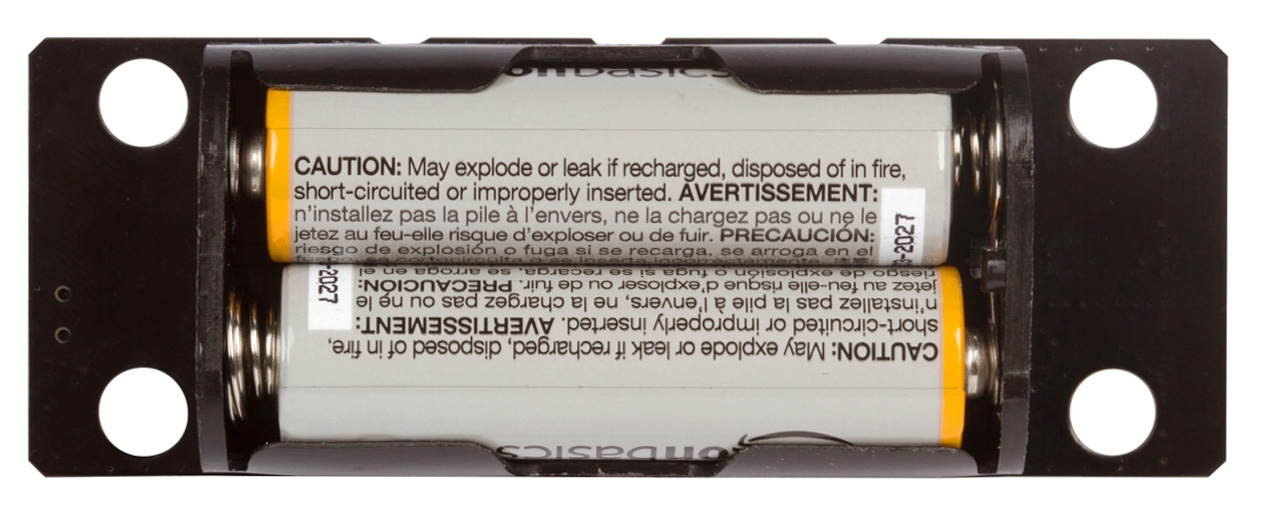
Power Switch
The Battery Powered Sensor Node incorporates a physical power switch, which is mounted on the circuit board. This is initially turned off to prevent the bundled AA batteries from running down before you receive them. This switch must be set as shown in the image below in order to power up the Sensor Node:
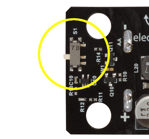
Until the switch is thrown, the Battery Powered Sensor Node will not function.
Environmental Sensors
The Battery Powered Sensor Node incorporates the following sensors:
| Sensor | Measured Quantity | I²C Address (8-bit) | Interrupt Pin | Datasheet |
|---|---|---|---|---|
| HTS221 | Temperature and humidity | 0xBE | hardware.pinE | Link |
| LIS2DH12TR | Motion in three axes | 0x32 | hardware.pinT | Link |
| LPS22HB | Air pressure | 0xB8 | hardware.pinX | Link |
Each sensor is supported by an Electric Imp library. Please consult each sensor’s library documentation (click on the sensor’s name in the table above) for guidance on making use of the sensors in your application, and to get the latest version of the library.
Note The LIS2DH12TR intentionally makes use of the LIS3DH library as these two devices are functionally equivalent.
The LIS2DHTR and LPS22HB provide interrupt lines to signal deviations from pre-programmed levels; the HTS221 has an interrupt line to signal the availability of a new reading. The table above lists the imp003 pins to which these pins are connected. The LPS22HB and LIS2DH12TR interrupts are also connected to the imp003’s wakeup pin, hardware.pinW, via an OR circuit and can therefore also be used to wake the Sensor Node from deep sleep. To do so, hardware.pinW must be configured as follows:
hardware.pinW.configure(DIGITAl_IN_WAKEUP);
RJ-12 Connector
The RJ-12 connector is a six-pin connector providing connectivity for 1-Wire, serial and I²C devices. The connectors pins are as follows:
| Pin | Function |
|---|---|
| 1 | I²C SCL / uartFG TX* |
| 2 | Not connected |
| 3 | 1-Wire DQ* |
| 4 | GND |
| 5 | VBAT or 3V* |
| 6 | I²C SDA / uartFG RX* |
- Requires enabling via imp003 GPIO — see descriptions below.
1-Wire
The DQ pin connects to the Sensor Node’s imp003 via UART pins D and M, and is therefore accessed through the hardware.uartDM object. These pins are connected to the RJ-12 via a 4.7kOhm resistor and a Shottky Diode to provide 1-Wire bus signalling via UART. You will need to include Electric Imp’s 1-Wire support library in your device-side application code. This library provides tools to enumerate 1-Wire devices and to interact with them.
For more information, please see the 1-Wire library page and the Developer Guide ‘Implementing 1-Wire Buses in imp-enabled Devices’.
To make use of 1-Wire, you must drive the Sensor Node’s 1-Wire enable pin (imp003 hardware.pinS) High.
I²C And UART
Pins 1 and 6 of the RJ-12 connector can be used to connect UART and/or I²C devices. The 1-Wire enable pin (imp003 hardware.pinS) must be driven High if you wish to activate the on-board I²C 4.7kΩ pull-up resistors and/ or power on the RJ-12 pin 5. The I²C bus is the imp003’s hardware.i2cFG; the UART bus uses hardware.uartFG. The connector pins are linked to the imp003 module as follows:
| RJ-12 Pin | imp003 Pin | I2C Role | UART Role |
|---|---|---|---|
| 1 | Pin F | SCL | TX |
| 6 | Pin G | SDA | RX |
VBAT/3V0
Pin 5 is enabled by driving the 1-Wire enable pin (imp003 hardware.pinS) High.
The VBAT/3V0 could be the direct value battery voltage, 3V0 or 3V3. The choice is made by setting the following imp003 pins:
| POWER_EN |
3V3_EN (GPIO Pin Y) |
VBAT/3V0 Voltage |
|---|---|---|
| 0 | N/A | Battery Voltage* |
| 1 | 0 | 3.0V |
| 1 | 1 | 3.3V |
- If the battery voltage is more than the 1.9V threshold, then this is the minimum voltage available on the enabled VBAT/3V0 line.
Though the POWER_EN pin is not connected to an imp003 GPIO pin, it can be controlled using the imp API method imp.setpoweren(). POWER_EN is low when the imp003 is in deep sleep, or the WiFi is disabled for some other reason (the imp003 has woken but not yet attempted to connect to the server, or Squirrel has called server.disconnect()). To set POWER_EN high in these circumstances, call
imp.setpoweren(true);
You can then set 3V3_EN as you require by calling
local state = <1 or 0> // 1 -> 3.3V, 0 -> 3.0V
hardware.pinX.configure(DIGITAL_OUT, state);
Remember, POWER_EN will be enabled automatically when WiFi is active.
NTC Thermistor
The Battery Powered Sensor Node motherboard provides two pads to which an NTC thermistor may be soldered. To make use of such a device, the Sensor Node’s NTC enable pin (imp003 pin hardware.pinK) must be driven High. The thermistor can then be read via hardware.pinJ.
Electric Imp provides a Thermistor library to help you manage and utilize a connected thermistor.
FTDI
The Battery Powered Sensor Node motherboard provides header pins (J2) which can be connected to an FTDI cable for debugging. The header provides GND, RX and TX pins — the latter two are connected to the imp003’s hardware.uartQRPW bus (pin Q TX, pin R RX).
Power
The Battery Powered Sensor Node is fitted with reverse voltage protection and under-voltage lockout circuitry to, respectively, protect the unit against incorrect battery insertion, and to provide a graceful shutdown when the batteries can no longer supply sufficient power to the sensors. This circuitry is detailed in the schematics (see link below).
The Sensor Node must be powered by two AA batteries. We recommended Li/FeS2 cells (eg. Energizer L91).
User-controllable Status LEDs
The Battery Powered Sensor Node motherboard provides two user-controllable status LEDs, one blue, the other green. These are each controlled by an imp003 GPIO pin:
| LED | imp003 Pin |
|---|---|
| Green | Pin U |
| Blue | Pin P |
Each pin should be driven low to illuminate its LED.
Note If WiFi is disabled — for example, when the Battery Powered Sensor Node wakes from deep sleep — then the blue LED will not be powered. Call spiflash.enable() to provide it with power.
Programming The Battery Powered Sensor Node
Sample Code
Additional Programming Resources
- imp003 Pin Mux
- imp003 Datasheet
- Electric Imp 1-Wire Library
- Implementing 1-Wire Buses in imp-enabled Devices