April Development Board
April is a very simple board with the minimum required components for an imp001-based device.


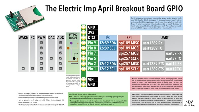
Pinout chart
Power
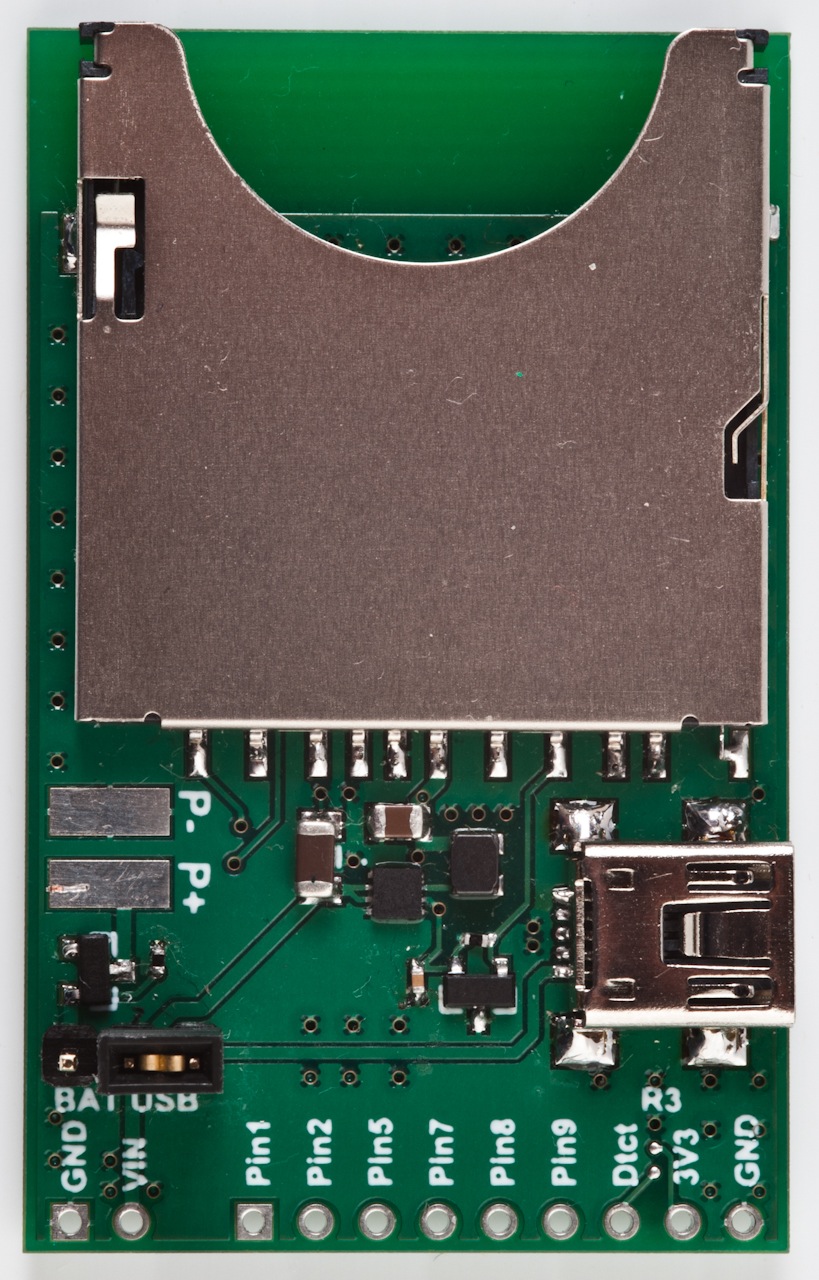
Power can be supplied using a USB Mini-B cable from a USB Charger or a standard USB Port, though the data lines are not connected to anything. Optionally, a battery connector can be soldered to the battery pads P+ and P-. April can operate from any DC voltage from 3.3V to 17V, and tolerates voltages down to -12V. This is helpful for any application with removable batteries where they may be inserted backwards by the user. You may select between USB power and battery power by placing a shunt on the power select header. Please note that April does not have any circuitry for charging a battery and you should never short USB power to the battery pack.
April uses the TI TPS62172 DC/DC Buck Power supply for 3.3V. It can provide an additional 100mA at 3V3 to any boards connected to April. However, if your application requires more than 100mA at 3V3, it must have its own supply.
The three-pin jumper allows selection of the DC input source: the jumper between the middle pin and the side labeled USB for USB power, and the other way for battery pack power (soldering the input leads onto the P+ and P- pads).
Signals
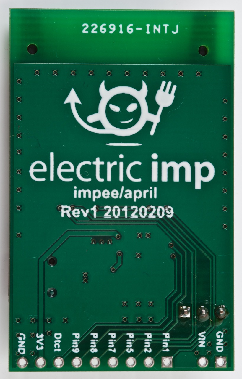
All of the signals from the imp come out to a header. For descriptions of pin of function see the imp001 pin mux.
Card Detect
If your application requires the card detect signal, it must be pulled up by soldering an 0402 resistor R3 or on an external board. The signal is connected to GND whenever a card is present in the slot, so we recommend using a 100kΩ or higher resistor to save power.
VIN
This pad is connected to the input voltage being fed to the board — either the USB 5V supply or the reverse-voltage protected battery pads.
